关键词 > MCBEND
Practical Monte Carlo using MCBEND
发布时间:2025-09-29
Hello, dear friend, you can consult us at any time if you have any questions, add WeChat: daixieit
Practical Monte Carlo using MCBEND - Assessed Exercise
Updated 13/3/2025
This MCBEND Monte Carlo modelling assessment is for PTNR & NDAWM students. It is set during the fifth teaching session, and we recommend that students have a go at the problem during the final workshop. Use the MCBEND User Guide, lecture slides and workshop example files to aid you before asking for help.
The problem is divided into three parts, all of which use the same starting MCBEND Base Model. The details required for the MATERIAL GEOMETRY, MATERIALS SPECIFICATION and SCORING units are presented here before the exercises are set. The assessment will take the form of a single short report with a maximum length of six pages of text. This can be supplemented by up to four pages of tables and figures. You will also need to submit your MCBEND input and output files.
The report will describe all three exercises, must be in pdf format and have the following structure:
Abstract: A brief description of the work and the key conclusions (200 words max.)
1. Introduction: Explain in outline what you have done, providing some background information on the methods used.
2. Method:
2.1. Describe your MCBEND model, using figures and tables where appropriate.
2.2. Exercise 1: Describe the computational methods used for Exercise 1 including what nuclear data you have used.
2.3. Exercise 2: Describe the computational methods used for Exercise 2 including what nuclear data you have used.
2.4. Exercise 3: Describe the modelling changes introduced for Exercise 3 and your approach to solving the problem.
3. Results:
3.1. Exercise 1: Present your results for Exercise 1 – referring to results tables and figures where appropriate. Choose which results to present with the questions in mind.
3.2. Exercise 2: Present your results for Exercise 2 – referring to results tables and figures where appropriate. Choose which results to present with the questions in mind.
3.3. Exercise 3: Present your results for Exercise 3 – referring to results tables and figures where appropriate.
4. Analysis & Discussion:
4.1. Exercise 1: Use appropriate analysis and discussion to answer the set questions.
4.2. Exercise 2: Use appropriate analysis and discussion to answer the set questions.
4.3. Exercise 3: Use appropriate analysis and discussion to answer the set questions.
4.4. Monte Carlo radiation transport question
There may be other relevant points to make about your results and analysis, especially if you have gone beyond the required exercises. Feel free to include these in your results and discussion, subject to the total page limit.
5. Conclusions: What conclusions can you draw from the modelling you have done?
Target Readership: Write the report as if it is to be read by somebody who is already familiar with Monte Carlo radiation transport methods and MCBEND.
Although no mark scheme is provided the allocation of marks is heavily weighted towards the accuracy of your MCBEND models, your results, how you present them and the conclusions you draw from them.
We will not assess any textual material within the report beyond the first six pages, but we will look in detail at your figures and tables. A single input file needs to be submitted for each of the three exercises along with its corresponding MCBEND output file. The input files need to be separate text documents suitable for immediate input to MCBEND (i.e. not pdf or WORD files and not appended to the report). These will be assessed along with your report.
Your report is due for submission electronically using the Canvas system. You must include your name within a comment at the top of your MCBEND input files; you will be assessed on your general use of comments.
1 The MCBEND Base Model Geometry:
You are required to construct a MCBEND model of a bundle of 100 fuel elements held within a water-filled lead container. A completed MCBEND model is shown in Figure 1. This is not necessarily a fully realistic nuclear industry scenario; it has been designed to enable you to demonstrate the skills you have learned on the course. The details required to build the model are as follows.
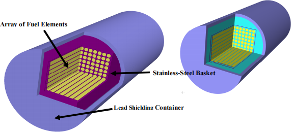
Figure 1. Bundle of Fuel Elements within a Lead Shielded Container Left: with water removed. Right: with all materials present.
1.1 The Fuel Elements
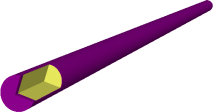
Figure 2. A Fuel Element
The fuel elements are made from metallic uranium fuel rods, with enrichment in 235 U of 1.0% by weight.
The rods are clad in stainless steel of radial thickness 0.25 mm. The clad thickness at each end of the rod is 5 mm.
Fuel rod radius is 12.5 mm and the fuel rod length is 1100 mm.
The fuel rod and its clad together make up the fuel element (see Figure 2).
1.2 The Fuel Element Bundle
One hundred fuel elements are arranged in a square array of 10 x 10 (you can assume the elements are held in position by an unknown structure, which you do not need to model). The lattice pitch in both directions is 30 mm and the space between the fuel elements is filled with water.
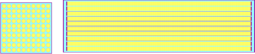
Figure 3. A Bundle of 100 Fuel Elements Within a Stainless-Steel Basket
Left – cross-sectional end elevation. Right – cross-sectional side elevation
The array of fuel elements is held centrally within a stainless-steel basket of wall thickness 5 mm. Basket internal widths are 310 mm . Basket internal length is 1140 mm. Basket wall thickness is 5 mm. The basket fully encloses the bundle of fuel elements.
1.3 The Shielded Container
The basket containing the array of fuel elements is held centrally within a lead cylindrical shielded container. Again, this is due to an unknown structure that does not require modelling. This lead shield has an internal radius of 235 mm and an internal length of 1250 mm. Its radial and end thicknesses are both 25 mm.

Figure 4. Lead Shielded Container
Left – cross-sectional end elevation. Right – cross-sectional side elevation 1.4 Material Densities
The following materials are to be used for the model.
|
Material |
Density (g/cm3) |
Used for |
|
Uranium (enriched to 1wt%) |
18.0 |
Fuel rods |
|
Stainless Steel |
7.9 |
Fuel element clad, Basket |
|
Water |
1.0 |
Fills the gaps inside the shielded container |
|
Lead |
11.0 |
Shielded container |
Table 1. Materials Required for the MCBEND Model
1.5 Scoring Geometry
You are required to score dose rates at 1 m from the three external surfaces of the shielded container (the end faces and the cylindrical surface). Hint – two of these are equivalent to each other.
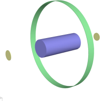
Figure 5. Scoring Regions 1 m from the External Surfaces of the Container
Each scoring region shall be 10 mm thick and straddle the required scoring distance (1 m).
The end scoring region(s) shall be cylinders coaxial with the container and have a diameter equal to half the external diameter of the container.
The side scoring region shall be centred about the mid-point of the container and have a length of 200 mm. Figure 5 shows what they should look like in the model.
You are required to score dose rates using the ICRP74 fluence-to-dose response function in MCBEND’s built-in response library (see Table 1 in Section 3.7.3 of the User Guide).
The model defined in this section is referred to as the Base Model.
2 Exercise 1: Gamma-Ray Problem
The first exercise requires you to define a specified source of gamma-rays within the MCBEND Base Model and to run Monte Carlo simulations to score the required dose rates. You will then need to change some aspects of the model to investigate how dose rates change.
The fuel rods within the bundle have been uniformly irradiated in a nuclear reactor so that along their entire length they all emit the same gamma-ray spectrum shown in Table 2.
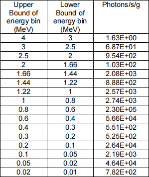
Table 2. Photon Emissions from the Irradiated Fuel in the Model
The values in the right-hand column represent the number of photons emitted per second per gram of irradiated uranium within each of the energy groups defined by the first two columns.
Define a source within your MCBEND model to represent the gamma-ray emission from your fuel. Use the photon Standard 22 group scheme to score Contributions to Responses as well as the total responses.
Gamma Case 1. Run the simulation for long enough to score reliable dose rates within your scoring regions.
Gamma Case 2. Replace the lead shield with Cast Iron (use the MCBEND library definition) and run the calculation again.
For each result:
What is the total source in your model (gamma-rays per second)?
Explain in the Method section of your report what you did.
Present your results in the Results section and discuss and compare them in the Analysis section.
Do you think the results are reliable?
Which are the most significant dose rate scoring groups and why?
Don’t forget stochastic uncertainties.
Comment on and explain the relative dose rates in the different scoring regions.
Comment on how dose rates vary between your simulations and explain your observations. Which of the container materials makes the best shield? What other materials may make good shields? Discuss the relevant gamma-ray interactions. Feel free to comment on anything which you think may be of relevance.
Submit the MCBEND input and output files for Gamma Case 1 (with water present and a lead shield) with your report. These files must be plain text so the examiners can run your models.
3 Exercise 2: Neutron Problem
The second exercise requires you to define a specified source of neutrons within the MCBEND Base Model and to run Monte Carlo simulations to score the required dose rates. You will then need to change some aspects of the model to investigate how dose rates change.
Go back to the MCBEND Base Model and redefine the source to be fission neutrons from 235 U. The intrinsic source strength is 10 neutrons per second per gram of uranium2. In reality, such neutrons would come from the decay of actinides present within the irradiated fuel, but you can treat them as having a fission source spectrum (U235). Since the fuel contains fissile nuclides, secondary fission neutrons will also be produced and may well dominate. Remember that this is not the default situation in MCBEND, neutron multiplication by fission needs to be switched on.
Use the neutron Standard 28 group scheme to score Contributions to Responses as well as the total responses.
Neutron Case 1. Run the simulation for long enough to score reliable dose rates within your scoring regions.
Neutron Case 2. Run the simulation again, but this time with water drained from the container and basket.
What is the total source in your model (neutrons per second)? This should be the intrinsic source before any secondary fission neutrons.
For each result:
Explain in the Method section of your report what you did.
Present your results in the Results section and compare and discuss them in the Analysis section. Do you think the results are reliable?
Which are the most significant dose rate scoring groups and why?
Don’t forget stochastic uncertainties.
Comment on how dose rates vary in each case and explain your observations. Discuss the neutron interactions that occur and the significance of the presence of water in the container.
Submit the MCBEND input and output files for Neutron Case 1 (water present and a lead shield) with your report. These files must be plain text so the examiners can run your models.
4 Exercise 3: Shielding Problem
Transport regulations require that, for this type of package, the maximum dose rate 1 m away from the external surface must be no more than 0.1 mSv/h. However, due to weight handling constraints for this package, the mass of shielding material used needs to be minimised. A shielding assessment is required to help decide what material the shielding container should be made from, what thickness the containers walls need to be to meet the maximum dose rate criterion, and what mass of shielding material this represents. You should assume the following:
. the package does not hold any water,
. the fuel bundle and basket remain unchanged from that in Sections 1.1 and 1.2 (but now they are dry),
. the neutron and gamma-ray source terms are the same as those stated in Sections 2 and 3,
. the inner dimensions of the container remain unchanged,
. the dose rate contribution from neutron-induced secondary gamma-rays is negligible.
You will investigate three container materials: lead, cast iron and concrete.
Use MCBEND calculations to determine the combined gamma-ray and neutron dose rates for a variety of wall thicknesses for each container material to find the thinnest container wall required to meet the external dose rate requirement. Use these minimum wall thicknesses to calculate the minimum mass of each shielding container needed to meet the dose rate requirement. You can ignore the fixed mass of the fuel element bundle for this comparison.
Within the report state the minimum container wall thicknesses you calculate as well as the corresponding mass for each of the three shielding materials. Which material meets the maximum dose rate requirement with the lowest mass? Using your knowledge of radiation transport discuss the reasons why you think this material is the most effective of the three for at shielding with the least mass.
Submit the MCBEND input and output files for one of your Exercise 3 Concrete Cases with your report. These files must be plain text so the examiners can run your models.
4.1 Monte Carlo Radiation Transport Theory
One final question. In this assessment the array of fuel elements has been defined explicitly using an array of fuel rods, clad and water. However, when a whole reactor model is built (e.g. for a PWR) it is common practice to model some of the fuel assemblies using “smeared” materials (consisting of a homogeneous mixture of fuel, clad and coolant) rather than explicitly representing each fuel pin, even though the latter option would be more geometrically accurate. With reference to what you know about Monte Carlo collision processing explain why this smeared approach may be preferable for complex whole reactor calculations.
