关键词 > FMET
Fluid Mechanics and Energy Transfer (FMET)
发布时间:2025-02-22
Hello, dear friend, you can consult us at any time if you have any questions, add WeChat: daixieit
Fluid Mechanics and Energy Transfer (FMET)
Laboratory experiment FMET2 - Momentum principle and impact of jets
Learning outcomes
a) To observe what happens when a water jet impinges on flat and curved plates for a range of discharges.
b) To appreciate the use of the momentum equation when determining forces.
1. Introduction
The aim of this experiment is to study the behaviour of water jets and their impact on surfaces, and in so doing to learn something about the application of the momentum principle to fluid flows. In solid body mechanics, the application of Newton's second law of motion is relatively straightforward. The mass is clearly that of the body and the applied force and acceleration are handled in terms of vector quantities. In fluid mechanics, the concept of a 'control volume', into and out of which the fluid flows, must be adopted instead. The momentum per second crossing the surfaces of the control volume are the equivalent of the forces in solidbody mechanics. This experiment involves measuring the forces that a water jet discharging from a nozzle imposes on flat and curved surfaces, and comparing these forces with those that would be expected from an application of the momentum principle to the control volume that surrounds the water jet.
2. Theoretical considerations
If a jet of fluid impinges on a flat plate, and is deflected through 90 degrees, it is shown in lectures that the application of the momentum principle predicts that the force F on the plate will be:
F = ρQu = ρu2A (1)
where Q is the discharge, ρ is the density of water ( = 1000kg. m3), u is the jet velocity and A is the jet area. If a water jet impinges on a curved target that turns the flow through 180 degrees (i.e. back in the original direction) it can again be shown that:
F = 2ρQu = 2ρu2A (2)
Experimental apparatus and procedure
The apparatus is shown in Figure 1. It consists of a nozzle from which a vertical jet of water issues and impinges on one of two targets – a flat plate target and a hemispherical target. The former deflects the flow through 90° and the latter through 180° . Install the flat plate onto the lever arm taking care not to drop it into the apparatus. Adjust the nut holding the spring until the lever arm is horizontal when the lateral distance on the arm is zero (x = 0). Record on the table on the following page the nozzle diameter dn , the vertical distance z between the end of the nozzle and the plate, and the jockey mass m . Also calculate the nozzle area A . Turn on the apparatus, with the control valve closed. Set the jockey weight at its maximum A position and adjust the control valve, and thus the discharge until the lever arm is again horizontal. Record the distance along the lever arm, x, and the flow rate, Q. Reduce the discharge in 6 to 8 stages, recording Q and x each time. Replace the flat plate with the hemispherical cup and again adjust the spring tension to give x = 0 for the no flow condition. Repeat the procedure as for the flat plate.
Note that u , the velocity at the plate and is related to the velocity at the nozzle un by the expression for vertical motion in a gravitational field u2 = un(2) - 2gz where u + n = Q /A. Also the force exerted on the plate can be determined from taking moments about the spring balance pivot, which gives F × 0.150 = mgx.
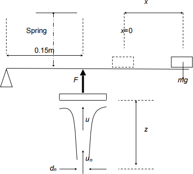
Figure 1 The experimental apparatus
3. Results
a) Complete the table on the following page for the flat plate target and plot the force measured with the spring balance system against that calculated from the momentum principle (equation (1)). Calculate the gradient of the graph.
b) Similarly plot the same graph for the cup target (with the value from the momentum principle taken from equation (2)). Again calculate its gradient.
c) Comment upon any differences in the measured gradients from those that would be expected.
Equipment parameters
Complete the following table
|
Nozzle diameter (m) |
Nozzle area A (m2) |
z (m) |
m (kg) |
|
10*10^-3 |
7.854*10^-3 |
35*10^-3 |
0.6 |
Flat plate target
Record the experimental results in the following table, and carry out the required calculations
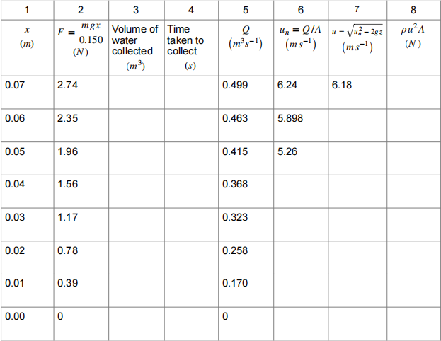
Plot a graph, either on the axes below, with column 2 as the x axis and column 8 as the y axis, and calculate the gradient.
Hemsipherical target
Record the experimental results in the following table, and carry out the required calculations
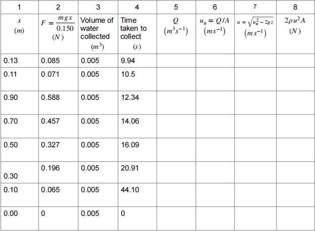
Plot a graph, either on the axes below, with column 2 as the x axis and column 8 as the y axis, and calculate the gradient.
Comment on the differences in the gradients from what would be expected.

Graph 1
Graph 2
