关键词 > MEEK16104
MEEK16104 ELECTRICAL MACHINES AND DRIVES Lab2
发布时间:2024-07-01
Hello, dear friend, you can consult us at any time if you have any questions, add WeChat: daixieit
MEEK16104
ELECTRICAL MACHINES AND DRIVES
Lab2
Design of DC motor speed control techniques using
MATLAB/SIMULINK
Aim
The aim of this experiment is to design, simulate and compare the different speed control techniques of a DC motor.
Objectives
The main objectives are:
• To design and simulate different speed control techniques of a DC motor. These techniques include three most common speed control methods, namely field resistance control, armature voltage control, and armature resistance control. The thyristorized techniques include using power electronic converters (Half converter, semi converter and full converter) to control the voltages.
• Make a comparative analysis of the different speed controller techniques.
Equipment and Materials
MATLAB/SIMULINK software.
Procedure
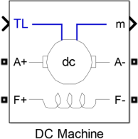
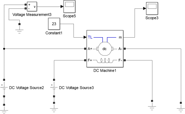
1. Find the input DC Motor in the component library of simulink, find the DC motor model, and drag it into the simulation interface, as shown in the following figure:
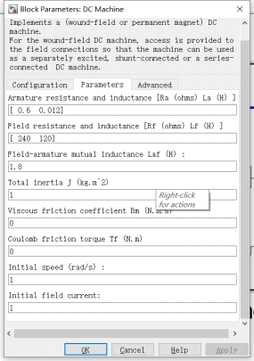
2. The selected DC motor parameters are shown in the figure below:
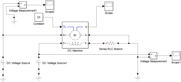
3. Build and analyze the following four simulation models: A, B, C, and D: A. The DC motor is directly connected to the resistance to start the control. The built simulation model is shown in the following figure:
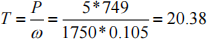
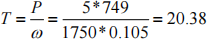
The maximum load torque is calculated as follows:
Under different load torques, the speed conditions are simulated respectively, as shown in the following table:
|
No. |
Load torque (Nm) |
Rotor Speed (rad/s) |
Remarks |
|
|
|
RF1=150Ω |
RF2=300Ω |
|
|
1 |
1 |
379 |
553 |
|
|
2 |
2 |
377 |
548 |
|
|
3 |
4 |
373 |
540 |
|
|
4 |
5 |
371 |
535 |
|
|
5 |
6 |
369 |
531 |
|
|
6 |
8 |
365 |
522 |
|
|
7 |
9 |
363 |
518 |
|
|
8 |
10 |
361 |
513 |
|
|
9 |
12 |
357 |
505 |
|
|
10 |
13 |
355 |
500 |
|
|
11 |
14 |
353 |
496 |
|
|
12 |
16 |
349 |
487 |
|
|
13 |
18 |
345 |
478 |
|
|
14 |
20 |
340 |
469 |
|
The torque-speed characteristics of different field resistances are shown in the following figure:
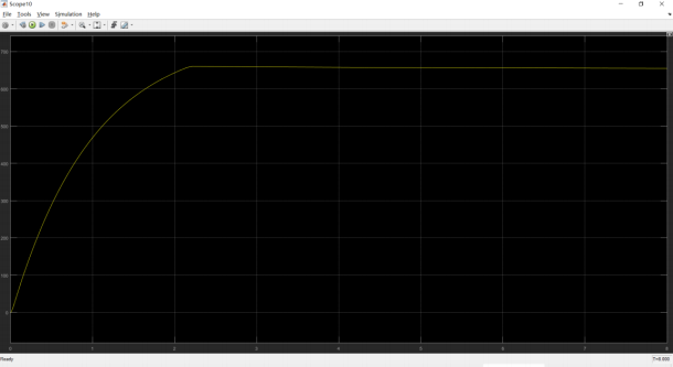
The speed waveform is shown in the following figure:
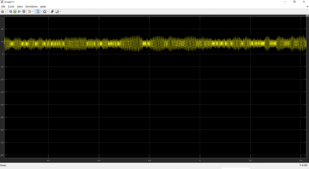
The current waveform is shown in the following figure:
B. DC motor with armature voltage start control
The built simulink simulation model is shown in the following figure:
The maximum load torque is calculated as follows:
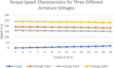
Under different armature voltages, the speed conditions are simulated respectively, as shown in the following table:
|
No. |
Load torque (Nm) |
Rotor Speed (rad/s) |
Remarks |
||
|
VA1 = 240 V |
VA2 = 200 V |
VA3 = 300V |
|||
|
1 |
1 |
193 |
161 |
241 |
|
|
2 |
2 |
192 |
160 |
240 |
|
|
3 |
4 |
191 |
160 |
240 |
|
|
4 |
5 |
190 |
159 |
239 |
|
|
5 |
6 |
189 |
158 |
239 |
|
|
6 |
8 |
188 |
157 |
239 |
|
|
7 |
9 |
188 |
157 |
238 |
|
|
8 |
10 |
188 |
156 |
237 |
|
|
9 |
12 |
187 |
155 |
236 |
|
|
10 |
13 |
187 |
155 |
236 |
|
|
11 |
14 |
186 |
154 |
235 |
|
|
12 |
16 |
185 |
153 |
235 |
|
|
13 |
18 |
184 |
152 |
233 |
|
|
14 |
20 |
183 |
151 |
232 |
|
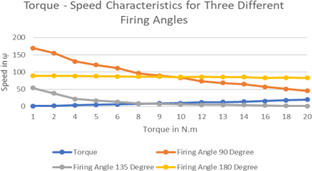
The torque-speed characteristics at different armature voltages are shown in the figure below:
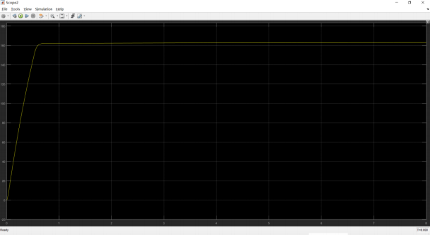
The speed waveform is as follows:
The current waveform is as follows: