关键词 > Civilengineering
Final Assessment
发布时间:2024-06-28
Hello, dear friend, you can consult us at any time if you have any questions, add WeChat: daixieit
Final Assessment - (Revision problems)
QUESTION 1
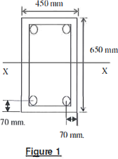
The columns of a reinforced concrete frame in a building are rectangular in cross-section as shown in the adjacent section (Figure 1).
They are reinforced with 4N32 reinforcing bars, one at each corner of the section of 500 MPa yield strength and 12 mm diameter lateral reinforcement (ties).
The interaction diagram is to be used for design of the columns for bending about the major axis, XX, is given in Figure 2. The concrete compressive strength fc is taken as 32 MPa.
a) Complete the strength interaction diagram by calculating the coordinates of points D, C, Band A shown in Figure 2.
b) Sketch the design strength interaction diagram in terms of
c) Assuming that the column is short, check if the column is adequate to withstand the design axial force N' = 1200 kN and design moment M* =
450 kNm. ie M's Mu and N's Nu, Use the strength interaction diagram of part (a).
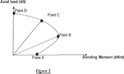
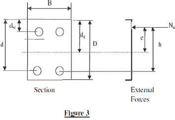
The significant points on the column strength interaction curve shown in Figure 2 above for the column section in Figure 3 below areas follows:
a) Point D - The capacity of the column in axial compression without bending moment Mu = 0 (ie Nuo on the strength interaction curve)
b) Point C - The moment capacity Mu and axial capacity Nu corresponding to the point on the interaction curve as decompression point.
c) Point B - The coordinate of the balanced point kv=0.55 ie. Mub and Nub,
d) Point A - The coordinate of pure bending Nu = O .
QUESTION 2
The Figure 4 shows a reinforced concrete floor of an office building supported on beams running in one direction. The floor is required to support alive load of 3 kPa in addition to the self weight of the slab. Density of concrete = 2400kg/m3, f'c = 32 MPa. Assume thickness of slab = 150 mm. Adopt N 12 bars (f5y= 500 MPa) as main reinforcement and clear cover= 25 mm.
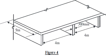
a) Check whether the trial slab thickness is adeqaute.
b) Calculate design moments and shears according to Cl 6.10 -Of AS3600 at support and mid-span sections.
c) Design slab for Flexural strength (i.e. calculate the tensile reinforcement required and check that the minimum reinforcement requirements are satisfied). Consider maximum design moment for the calculation.
d) Calculate the spacing of the reinforcement which would give you the reinforcement ratios determined in part (c).
