关键词 > MECH5125
MECH5125 Electric and Hybrid Drivetrain Engineering Academic Year 2023-24
发布时间:2024-06-22
Hello, dear friend, you can consult us at any time if you have any questions, add WeChat: daixieit
MECH5125 Electric and Hybrid Drivetrain Engineering
Academic Year 2023-24
Title: Single gear transmission for Formula E vehicle
Coursework Assignment: Detailed design of the shaft and spur gear pair
Weight: 40% of module mark.
Work type: Individual Assignment.
Deadline: 21 March 2023 at 12 noon.
Submission method: Individual report - Paperless via Minerva (Turnitin)
(report must include 2 detailed engineering drawings:
first of a shaft and second of a gear).
Feedback: Written via Minerva and in class feedback session.

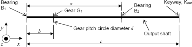
( for illustration only, you need to choose your own configuration )
Many modern electric vehicles have a single stage transmission fitted including Formula E cars. This is possible due to high torque at low revs and wide range of rotational speed delivered by electric motors. In this assignment, you will look in details at design process of simplified version of such transmission components.
The aim of the assignment
The aim of this work is to reinforce your understanding of the theory and design principles that underpin the detail design of a power transmission shaft and gears. This is achieved by getting you to design such a shaft and spur gear pair that meets your individual specification. You will first produce a concept design on the assumption of static loading and then go on to develop a detail design that takes into consideration the ability of the shaft to sustain cyclical loading which impacts on the fatigue life of the component.
You will each have ownership of a unique transmission specification, defined by a set of parameters. This data will be augmented by generic data that is common to all. These parameters will be fixed and you will not be able to alter their values.
Design Specification Parameters
You will receive individual design specification parameters from the table below. Full list of parameters is available in Assessment section on Minerva website of the MECH5125 module.
|
Parameter |
Symbol |
Unit |
A |
B |
C |
|
Centre distance between bearings |
a |
mm |
155 |
165 |
175 |
|
Location of gear centre between bearings |
b |
mm |
80 |
88 |
95 |
|
Location of centre of exit keyway or spline |
c |
mm |
225 |
235 |
255 |
|
Power to be transmitted through the transmission |
P |
kW |
150 |
160 |
170 |
|
Rotational speed of input shaft (Electric motor) |
w |
103 rpm |
16 |
17 |
18 |
|
Vehicle top speed |
v |
km/h |
200 |
210 |
220 |
Generic information
There are several generic pieces of information, that are required to enable you to complete the assignment and these are defined in the table below. This generic data applies to all the individual power transmission shaft configurations.
|
Generic Data |
||
|
Parameter |
Value |
Units |
|
Wheel rolling radius |
350 |
mm |
|
Pressure angle of gear |
20 |
Degrees |
|
Bearing life, output shaft |
300 |
Millions of revolutions |
|
Failure criterion for output shaft |
MSST |
- |
|
Yield stress of output shaft |
385 |
MNm-2 |
|
Ultimate tensile strength of output shaft |
770 |
MNm-2 |
|
Yield stress of key |
290 |
MNm-2 |
|
Factor of safety for output shaft |
1.6 |
- |
|
Factor of safety of key |
1.6 |
- |
|
Final Drive ratio |
Reasonable assumption required |
|
If you find the General Data too restricting for your design you can change them, however please justify the change made.
Please include in your report any other assumptions or constrains you have made during the design process.
Assignment Report Part 1: Concept design of the gearbox shaft and spur gear pair
Using the data contained in the power transmission shaft specification, you will determine:
• Overall gear ratio of the driveline,
• Gear ratio of the transmission,
• Diameters of the spur gear pair,
• Minimum face width of the gears,
• The location of the critical shaft cross section,
• The minimum allowable diameter for the shaft,
• The equivalent dynamic bearing load at each bearing,
• Type of the geometry (keyway/spline) located at the critical cross section of the shaft.
The shaft is the output shaft within a single stage reduction unit and supports a straddle mounted spur gear, G1, between two bearings, B1 and B2, whose locations are as indicated in the section Design Specification Parameters. The torque leaves the shaft through a standard keyway or spline (that will connect the shaft to a co-axial coupling) at the right-hand end of the shaft. A lip seal is to be placed between the right-hand bearing B2 and the keyway to prevent ingress of any contaminants to the unit. The bearings are located on the shaft using either conventional bearing nuts and lock washers or external circlips. The spur gear is to be radially located on the shaft using a standard key or spline whose length does not exceed the axial dimension of the gear. The gear must also be axially located. Assume steady state operation.
Assignment Report Part 2: Detailed design of the shaft and spur gear pair
Detailed Design
Using the outcome of part 1 (that made use of a static load case), you will develop a detailed design for your power transmission shaft and demonstrate, how it will meet the design specification under dynamic loads.
Include the table or list with all assumptions made during the design process. Include one or two sentences justifying each assumption.
The designed spur gear should be optimised for lightweight design. Design and optimisation process could be done for example using Generative Design method in Autocad Fusion 360 software available in the department or other suitable methods.
Calculate output power of your designed gearbox. To obtain gears efficiency values you will have to measure and calculate it using practical setup that will be available for this module. The practical of Gears Efficiency Experiment is described in separate file available in Assessment section of Minerva website of the module. The practical will be carried out in randomly selected small groups of 5 students.
Detailed Engineering Drawings
As an appendix in your report submit two detailed engineering drawings:
1) A detailed drawing of spur gear from the output shaft,
2) A detailed drawing of the output shaft of the power transmission.
The drawing must show all information, including fillet radii and tolerances as appropriate, surface finish, material treatment etc … to inform manufacture.
Include the table describing unique part number, author, date, revision number etc …
The detail drawing is NOT the layout drawing and so does not require you to show bearings etc in position along the shaft. Drawings can be prepared in SolidWorks, Autocad Fusion 360 or any other CAD software, good quality handmade drawing are also perfectly fine. Content and completeness of the drawings
Submission
1. Each group is required to submit the results of practical session and calculations of the spur gear efficiency (one document per group).
2. Each student is required to submit summary of his own contribution to the group and assessment of other group members contribution.
3. Each student is required to submit an individual report via Minerva, word limit is set to 3000, however shorter reports are perfectly acceptable and preferred.
Words limit refers to the main report only and front page and FMEA table does not count toward the limit. The report must include two detailed engineering drawings one of the shaft and one of the gear.
You can use PDFsamto merge the report PDF with the drawing PDFs.
https://github.com/torakiki/pdfsam/releases/download/v3.0.0.RELEASE/pdfsam-3.0.0.RELEASE-bin.zip
Marking scheme
Group work
• 10% Result of the practical group work, including the effectiveness of you contribution to the group dynamics (AHEP4 M16).
Individual work
• 10% Introduction and literature review of the Formula-E driveline (1 page max),
• 15% Concept Design and initial assumptions (refer to the bullet point in Concept Design section),
• 10% Failure Mode and Effect Analysis (FMEA) table taking into account all the transmission components as a whole system,
• 15% Justification of the detailed design of the gear, based on initial calculations and optimisation,
• 20% Justification of the detailed design of the shaft, based on initial calculations and optimisation,
• 10% Quality and completes of the detailed drawings of the shaft and gear,
• 10% Discussion and conclusions.
Use of the Artificial Intelligence technology
Category: RED - the use of artificial intelligence is not allowed in this assignment.
