关键词 > EEET4057
EEET4057 Power System Fundamentals Study Period 2 Exams, 2020
发布时间:2024-06-18
Hello, dear friend, you can consult us at any time if you have any questions, add WeChat: daixieit
EEET4057 Power System Fundamentals
Study Period 2 Exams, 2020
Section A: Multiple Choice
[10 marks, recommend time: 10 mins.]
Question 1 [10 marks]
Circle the correct answer for each question [1 mark per question]
1. You are told that one of the ABCD parameters of a transmission line is equal to 0.987 ∠56.87°. Which parameter does this correspond to?
a. A and D.
b. B.
c. C.
d. D and B.
2. A transmission line increases the number of conductors per bundle from 1 to 4, whilst maintaining the same conductors and geometric mean distance. Which of the following parameters is increased?
a. The resistance.
b. The inductance.
c. The capacitance.
d. The characteristic impedance.
3. A regulated bus has which two parameters that are fixed?
a. Voltage magnitude and voltage angle.
b. Voltage angle and real power.
c. Real power and voltage magnitude.
d. Real and reactive power.
4. Part of a power system has 5 active loads, 4 buses, 3 reactive loads and 2 transformers. Which of the following statements is correct?
a. There is one base power and two base voltages.
b. There is one base power and three base voltages.
c. There are two base powers and two base voltages.
d. There are two base powers and three base voltages.
5. Consider a 3-phase Y-connected load. If it is now connected in Δ, whilst the supply voltage is unchanged, which quantity increases by a factor 3?
a. Phase impedance.
b. Phase voltage.
c. Line voltage.
d. Line current.
6. The impedance of a load is given as – j6 Ω. What type of load is this?
a. Purely capacitive.
b. Purely inductive.
c. Purely resistive.
d. Resistive and capacitive.
7. The objective of a power system is to generate electric energy:
a. Economically.
b. With fixed voltage and frequency.
c. With maximum efficiency and reliability.
d. All of the above.
8. Which type of fault generally accounts for 80-90% of all faults experienced in power systems?
a. Single-line to ground.
b. Double-line.
c. Double-line to ground.
d. 3-phase.
9. Which type of short-circuit faults can be analysed using single-phase equivalent diagrams?
a. Double-line.
b. Double-line to ground.
c. Single-line to ground.
d. 3-phase.
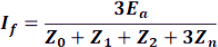
10. Consider the fault current, If, shown here. This represents which type of short-circuit fault?
a. 3-phase.
b. Bolted double-line.
c. Bolted double-line to ground.
d. Bolted single-line to ground.
Section B: Numerical Problems
[90 marks, recommend time: 110 mins.]
Numerical values highlighted indicate will be 1 of 9 values
Question 2 [11 marks]
0.82; 0.83; 0.84
0.85; 0.86; 0.87;
0.91; 0.92; 0.93
Two balanced 3‐phase loads are connected in parallel and supplied by a balanced, three‐phase 11 kV source. One load draws 121 kW at a lagging power factor of 0.85, whilst the other load draws a load of 66 kW + j21 kVAr. Assume a supply frequency of 50 Hz.
a) Draw the power triangle for the combined load and determine the overall power factor. [7 marks] PF = 0.8898 lag
b) Y‐connected capacitors are now installed in parallel with the combined loads. What value of capacitive reactance and capacitance is needed in each leg of the Y to make the source power factor equal to unity? [4 marks]
X1φ = -1,260.5 Ω;
C = 2.525 µF
Question 3 [14 marks]
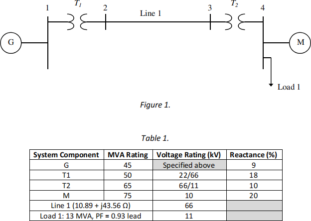
The single-line diagram of a particular power system is shown in Figure 1. The generator reactance is given for a voltage rating of 21 kV, whilst all other voltage ratings are shown in Table 1. Choose a base power of 100 MVA and a base voltage of 22 kV at the generator.
a) Calculate all reactances in pu. [10 marks]
b) Draw the impedance diagram and mark all impedance in this. [4 marks]
19; 20; 21;
22; 23; 24;
25; 25; 26
Question 4 [20 marks]
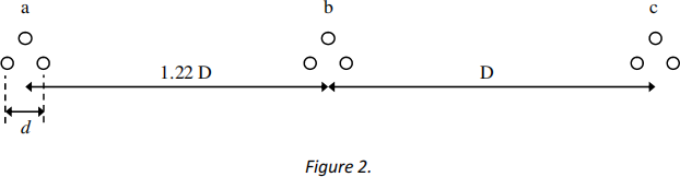
A 32 km, 132 kV, 3‐phase, single-circuit 50 Hz transmission line has a horizontal spacing as shown in Figure 2. Each phase of the line consists of a bundle of three ACSR FINCH conductors, where the GMR is 1.3258 cm, and the conductor diameter is 3.2842 cm. Calculate:
a) D if the geometric mean distance is 15.33 m. [3 marks] D = 11 m
b) The per‐phase inductance and the per‐phase shunt capacitance of the line. Assume bundle spacing, d = 0.45 m. [9 marks] L = 0.9408 mH/km; C = 0.01200 µF/km
c) Calculate the ABCD parameters, assuming the nominal π model. [8 marks]
0.42; 0.43; 0.44;
0.45; 0.46; 0.47;
0.48; 0.49; 0.50
A = D = 0.9994;
B = j 9.458 Ω;
C = 0.0001207 S
Question 5 [16 marks]
A 66 kV, 3-phase, 50 Hz, transposed transmission line has a per-phase series impedance of 0.2 + j0.46 Ω/km. The line is 25 km long and sending end transmits 103 MW + j47 MVAr at a sending end voltage of 69 kV. Calculate the:
a) The receiving end line voltage magnitude, current and total power. [13 marks]
b) The voltage regulation and transmission line efficiency. [3 marks]
22; 23; 24
25; 26; 27
28; 29; 30
a) |VRL| = 55.44 kV;
IR = 947.12 ∠ -24.53° A;
SR3φ = 90.95 MVA ∠ 10.16°
b) VR = 24.46%;
η = 86.92 %
Question 6 [8 marks]
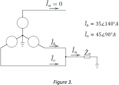
A 3-phase power system is shown in Figure 3, where phase a is open-circuited, whilst phases b and c are shorted to ground through impedance Zn = j 0.12 pu. Calculate the symmetrical components of Ia , given the currents shown.
0.09; 0.10; 0.11;
0.12; 0.13; 0.14;
0.15; 0.16; 0.17
Ia 0 = 14.998 ∠ 90° A;
Ia 1 = 22.98 ∠ -90° A
Ia 2 = 7.98 ∠ 90° A
Question 7 [13 marks]
The single-line diagram of a simple power system is shown in Figure 4, which experiences a 3-phase short circuit fault on bus 2, with a faut impedance, ZF, equal to j 0.20 pu. Each generator is represented by an emf behind the sub-transient reactance, Xdn ’’. All impedances are expressed in per unit on a common 100 MVA base. The following assumptions are made:
0.15; 0.17; 0.18;
0.19; 0.20; 0.21;
0.22; 0.23; 0.25
• Shunt capacitances and resistances are neglected.
• The system is considered on no-load.
• All generators are running at their rated voltage and rated frequency with their emfs in phase.
a) Using the Thevenin theorem, calculate the impedance to the point of the fault and the fault current. [5 marks]
b) Determine the line currents and the bus voltages during the fault. [8 marks]
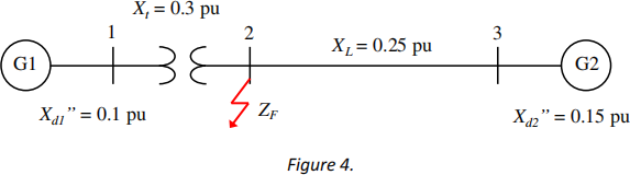
a) ZTH = j 0.20 pu;
IF = 2.5 ∠ -90° pu;
b) Ig1 = -j 1.25 pu;
Ig2 = -j 1.25 pu;
V2(f) = 0.50 pu;
V1(f) = 0.875 pu;
V3(f) = 0.8125 pu;
Question 8 [8 marks]
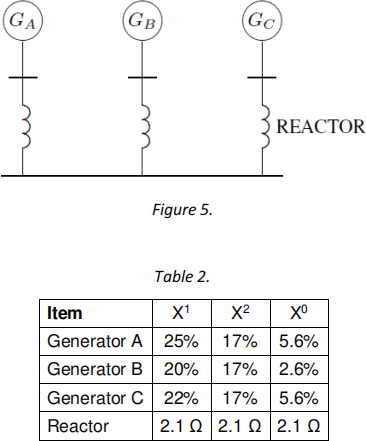
Calculate the zero-sequence network impedance for the system shown in Figure 5. The reactances of each generator and the reactors are shown in Table 2. Generators A and C are solidly grounded, whilst generator B has a neutral path reactance, Xn, of 0.21 Ω. The characteristic impedance is 21 Ω. [8 marks]
3.5; 7; 10.5;
14; 17.5; 21;
24.5; 28; 31.5
Z0 = j 0.052 pu
