关键词 > ENG4104
Power Systems 4 (ENG4104)
发布时间:2024-06-18
Hello, dear friend, you can consult us at any time if you have any questions, add WeChat: daixieit
Power Systems 4 (ENG4104)
Wednesday 27th April 2022
14:00–16:00PM
Attempt all Sections
Attempt ALL questions in Section A and any ONE from Section B.
Total 100 marks
Section A – Answer All Questions [75 marks]
Q1 Power System Analysis [58]
(a) Load Flow Analysis
(i) A transmission line of impedance ZL = 0.01 +j 0.05 pu links bus 1 to
bus 2. The voltage supplied to bus 1 is 1.0上0。pu and the load S2 at bus
2 is 1.1 +j 0.6 pu. Using the iterative method (calculate for three iterations: n = 0, 1, 2), determine the per unit voltage at bus 2. [8]
(ii) For the power system illustrated in Figure Q1a, the voltages at both ends of the power system are given as:
V1 = 1.05上δ。pu , V2 = 1上0。pu
The line reactance is given as j 0.05 pu. The real power at both ends of the line are P1 = P2 = 5pu. The complex power outputs SL1 and SL2 at the two buses are given as:
SL1 = 6 + j3pu, SL2 = 5 − j2pu
If the load SL3 at bus 2 is the same as the generator power at bus 1 (SL3=SG1), determine the generator power SG2 connected to bus 2 (using the formulae provided). [8]
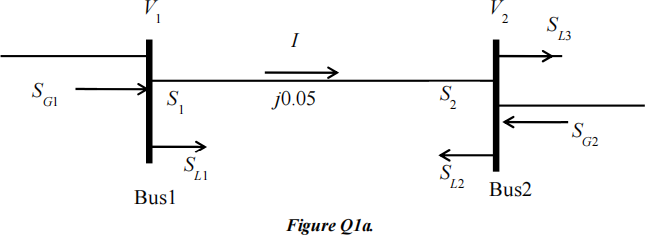
Useful formulae:
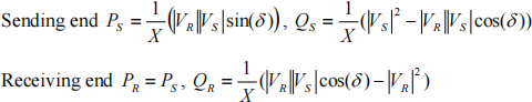
(b) Per Unit Analysis [10]
For the power system shown in Figure Q1b, calculate the per unit impedances of all components with given zone 1 voltage base 22kV and power base 100 MVA (for the system).
(Zone voltage bases 2 marks, per unit impedance calculation for each component 2 marks.)
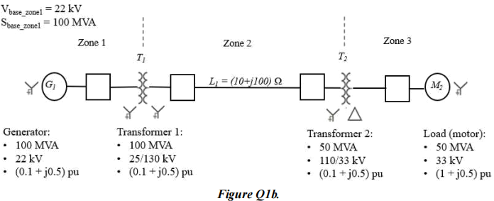
(c) Fault Level Analysis [14]
A simple electrical network is shown in Figure Q1c. All reactance values are shown in per-unit form to a common base voltage. Working to a base capacity of 100 MVA, estimate the short circuit capacity and fault current should a symmetrical three-phase fault occur on the 132 kV busbar at the position shown.
[per unit reactance calculations 6 marks, equivalent circuit and simplification 6 marks, capacity and current calculations 2 marks]
(d) Compare the load flow, per unit, and fault level analysis from aspects of: main purposes (6 marks), mathematical problems (6 marks), solving procedures (6 marks). [18]
Q2 Net-Zero Carbon Emission Context (Open-ended) [17]
(a) The Scottish Government has committed to 100% reduction in carbon dioxide emissions by 2045 (so-called ‘net-zero’, compared to 1990s level). In your opinion, by 2035 what percentage of electricity in Scotland should be derived from renewable resources and why? [5]
(b) Apart from Solar energy, describe another two main forms of renewable energy currently in use in the UK and for that indicate and explain three of their technical limitations with regards to the integration to power systems. (each form of energy 6 marks) [12]
Section B – Answer Any ONE Full Question [25 marks]
Q3 Power System Modelling [25]
(a) Transmission line modelling - explain why we need simplified transmission line models (3 marks) and under what conditions overheadline can be simplified as a single inductance (3 marks) and underground cable as a single capacitance (3 marks). [9]
(b) A three-phase 400 kV, 100 km transmission line has parameters
R = 0.005 Ω/km, XL= 0.05 Ω/km and XC = 1250 Ω/km, and delivers 950 MW to loads at 0.98 power factor (leading).
For the full distributed model, calculate matrix parameter B. [10]
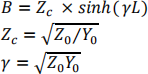
Useful formulae:
cosh(yL) = cosh(αL + jβL) = cosh(αL)cos(βL) + j sinh(αL)sin(βL) sinh(yL) = sinh(αL + jβL) = sinh(αL)cos(βL) + j cosh(αL)sin(βL)
(c) For different types of buses/nodes in load flow analysis, explain their definitions and possible numbers in a power system. [6]
Q4 Power System Operation [25]
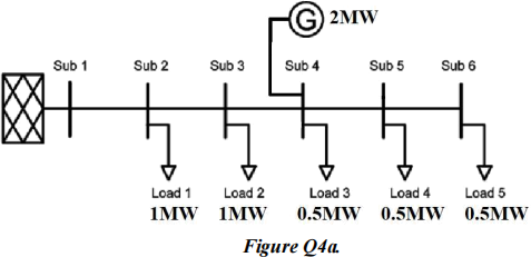
(a) For the system shown in Figure Q4a, explain with the aid of a diagram (load flow direction and voltage profile, 5 marks) and with simple calculations (ignore the power losses on the feeder, 6 marks), whether there is a voltage rise problem? [11]
List and briefly explain three possible solutions to reduce voltage rise issues (6 marks), with the voltage drop equation (2 marks). [8]
(b) Briefly explain the purpose of power filters (2 marks), and what are the advantages and disadvantages of active power filters (4 marks). [6]
