关键词 > CE335
CE335 DIGITAL SIGNAL PROCESSING Undergraduate Examinations 2019
发布时间:2024-06-15
Hello, dear friend, you can consult us at any time if you have any questions, add WeChat: daixieit
CE335-6-AU
Undergraduate Examinations 2019
DIGITAL SIGNAL PROCESSING
Question 1
(a) If x1(n) and x2(n) are odd sequences, determine whether y(n) = x1(n)x2(n) is an odd or an even sequence. [6%]
(b) Compute the convolutional sum h[n] = h1[n] ⊗ h2[n] when h1[n] = {0.5, 0.5}, for 0 ≤ n ≤ 1 and h2[n] = {0.5, 0.5}, for 0 ≤ n ≤ 1. If h[n] is the impulse response of an FIR filter, what is the type of this filter? [10%]
(c) One of the applications of Principal Component Analysis (PCA) is signal denoising. Describe the PCA algorithm. [7%]
(d) The moving average filter input-output equation is given by y[n] = 4/1 3Pi=0x[n − i], for n ≥ 0. Prove that the filter is a linear time-invariant (LTI) system. [10%]
Question 2
(a) The input-output relationship of a Finite Impulse Response (FIR) filter is given by [16%]
y[n] = x[n] − 2x[n − 1] − 3x[n − 2] + 3x[n − 3] + 2x[n − 4] − x[n − 5]
Compute the impulse response of the filter and then find the magnitude and the phase response. What is the group delay of this filter?
(Hint: Use Euler’s formulae cos(ω) = e jω+ 2 e−jω and sin(ω) = e jω−e−jω2j)
(b) Assume a signal x[n] = δ[n], 0 ≤ n ≤ 49 that is generated by sampling an analog signal xa(t) with sampling period 0.01 sec. [10%]
(i) Sketch the magnitude response of the signal. [6%]
(ii) The signal x[n] is filtered in the frequency domain with a low pass filter with cutoff frequency 20 Hz. Sketch the magnitude response of the filtered signal. [4%]
(Hint: Use the Discrete Fourier Transform (DFT) definition X(m) = N−1Pn=0x[n]WN mn with WN = e −j2π/N .)
(c) When we compute the DFT of a signal, we assume that the signal is periodic and that we observe a complete cycle of the signal. What happens if this assumption does not hold? How can one overcome this problem? [5%]
Question 3
A linear time invariant (LTI) system is realized by the flow graph shown in Figure 3.1
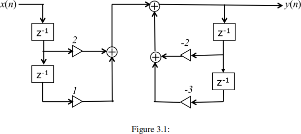
(a) Derive the relationship between the input x[n] and the output y[n] of the filter shown in the block diagram of Figure 3.1. [6%]
(b) Find the transfer function H(z) of the filter depicted in Figure 3.1 and determine the magnitude response of the filter. [10%]
(c) Find the zeros and the poles of the filter. Comment on the stability of the filter.
[Hint: az2 + bz + c = (z − z1)(z − z2), where z1 = −b + √ b2 − 4ac 2a and z2 = −b − √ b2 − 4ac 2a] [8%]
(d) Find a causal and stable filter that has the same magnitude response as the original filter.
[Hint: Consider the use of an all pass filter.] [6%]
(e) IIR filters do not have linear phase. Explain how this problem can be fixed offline and in real time. [6%]
