关键词 > Electricalengineering
Project Assignment
发布时间:2024-06-15
Hello, dear friend, you can consult us at any time if you have any questions, add WeChat: daixieit
Project Assignment
Report Due: April 24, 2024
Objective: Design a type-IV turbine power conversion system and evaluate its performance under different operation conditions by simulation in SIMULINK.
Specifications:
. Rated power PN = 4 MW
. Grid modeled as a 690 V (line-line RMS), 60 Hz voltage source behind an inductor Lg
. Turbine generator modeled as a 350 V (phase RMS), 40 Hz voltage source when operating at rated wind speed and power. The stator inductance is Ld = 45 μH; stator resistance is ignored.
. Inverter output filter inductor L = 90 μH
. Both the rectifier and the inverter use a 2-level VSC with 2.5 kHz switching frequency
. DC bus capacitance cdc = 30 mF
. DC bus voltage vdc = 1500 V
Design:
. PLL, dc bus voltage and dq-frame current control of the inverter with proper bandwidth and phase margin
. Generator dq-frame current control with proper bandwidth and phase margin. Assume the generator’s output voltage angle is directly measured and is available for dq transformation.
. A logic circuit to start the turbine according to the following sequence (with some delays in between to allow the transients generated by each action to settle):
o Connect the inverter to the grid
o Start inverter control to establish and stabilize the dc bus voltage
o Connect the rectifier to the generator
o Start rectifier control to extract desired amount of power from the generator
Simulation:
1. Operation with ideal grid (Lg = 0) and at rated wind speed
. Generator operates at rated speed; rectifier controlled to extract rated power
. Inverter outputs active power only
. Simulate both startup and steady state operation
2. Operation with ideal grid (Lg = 0) and at 70% wind speed
. Generator output voltage and frequency reduced to 70% of their rated values, and power reduced to 1.37 MW
. Inverter outputs a) active power only; b) active power and 1 MVA reactive power
. Simulate both startup and steady state operation
3. Operation with ideal grid (Lg = 0) and at 70% wind speed
. Keep the generator output voltage and frequency at their rated values
. Start the turbine with zero power output from the generator and rectifier
. Keep inverter reactive output power at zero
Additional assignments for graduate students. Undergraduate students do not need to do this part but will receive up to 50 additional points if they do.
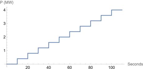
4. Change the grid impedance to Lg = 200 μH and implement a method to generate a q-axis reference current such that the grid voltage at the terminal of the turbine will remain at ~690 V as the turbine active output power varies. Simulate your design with the generator active output power increasing in 10% steps, as illustrated below.
5. If the simulation becomes unstable before it reaches 100% power, try to improve your control design to achieve operation at 100% power.
Report:
. Design of each of the control functions, including frequency responses of each loop gain
. Schematic of the implemented simulation model, including startup logic. In addition to the overall schematic, show details of individual blocks and explain their functions.
. Simulated turbine output current responses in each case, including overall responses and zoom-in view over 2-3 fundamental cycles to show details of the operation. For problem 4 and 5, also report the voltage at the terminal of the turbine.
. Your observation and evaluation of each simulation.
. Overall analysis and conclusions.
