关键词 > ECE5041
ECE 5041 Electric Machine Spring 2024 Homework 7
发布时间:2024-06-14
Hello, dear friend, you can consult us at any time if you have any questions, add WeChat: daixieit
ECE 5041 Electric Machine Spring 2024
Homework 7: 12%
_____Submit one single pdf file to include all results. Submit all simulation files too.
_____SUBMIT ALL FILES INDIVIDUALLY. NO ZIP FILES WILL BE ACCEPTED.
_____All simulation plots need to use data stored in “ToWorkSpace”. No credits will be given to screenshots of scopes.
A 3-phase Y-connected cage induction machine use the following machine parameters: Number of poles: 4
DC bus voltage: 750 V
Stator resistance: 0.1197 Ohm
Rotor resistance: 0.1336 Ohm
Stator leakage inductance: 1.1 mH
Rotor leakage inductance: 2.5 mH
Magnetizing inductance: 37 mH
Rotor inertia: 0.24 kg.m2
Friction factor: 0 N.m.s/rad
Power converter switching frequency 5 kHz
Problem 1. (30’) Induction machine torque vs speed curve simulation
1.1 (5’) Watch the tutorial and build your induction simulation model. Include a screenshot of your simulation model in the report. https://buckeyemailosu-my.sharepoint.com/:v:/g/personal/zhang_564_osu_edu/EcRCNSEeCqBGhBjBuhYWrTIB7IlTnCm JOajp5-7A4m39Dg?e=TI45PN
1.2 (2’) Simulate the model under 1800 rpm, observe the electromagnetic torque and rotor currents and write the values.
1.3 (6’) Simulate the model under the following speeds, observe and record the electromagnetic torque for every speed in the following table.
|
rpm |
0 |
200 |
400 |
600 |
800 |
1000 |
1200 |
1400 |
1500 |
1590 |
1620 |
1650 |
1700 |
1750 |
1800 |
|
Nm |
|
|
|
|
|
|
|
|
|
|
|
|
|
|
|
1.4 (4’) Plot the torque vs speed curve for this machine based on the simulation results in 1.3
1.5 (8’) Plot the following waveforms for the 1700-rpm simulation.
figure (1)
subplot(311) three phase voltages (2 fundamental cycles)
subplot(312) three phase stator currents (sametime window as subplot311)
subplot(313) electromagnetic torque (sametime window as subplot311 )
figure (2)
subplot(211) three phase rotor currents (2 cycles for rotor currents)
subplot(212) three phase stator currents (attention: sametime window as 211. Not 2 fundamental cycles as in figure1)
1.6 (5’) What is the measured rotor current frequency in 1.5? What is the calculated rotor current frequency in 1.5? Are they consistent? What is the rotor electrical frequency?
Comment on the relationship between the rotor electrical frequency, rotor current frequency and synchronous frequency (stator current frequency)
Problem 2. (50’) Induction machine simulation: indirect field orientation control
2.1 (10’) Watch the tutorial and build your own simulation model. Include screenshots of the
top-level simulation model and every subsystems in the simulation.https://buckeyemailosu- my.sharepoint.com/:v:/g/personal/zhang_564_osu_edu/ERJjnH_5sVdFnhfCh5x4Ex4B0NpUAx0 O9ixGE5HVOTl29w?e=roE36J
2.2 (10’) You want to use the stair generator and rate limiter blocks to produce a speed command profile. Read the user manual for “stair generator” and “rate limiter”
Stair generator:
https://www.mathworks.com/help/physmod/sps/powersys/ref/stairgenerator.html
Rate limiter:
https://www.mathworks.com/help/simulink/slref/ratelimiter.html
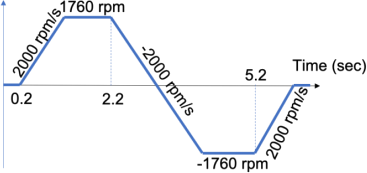
a. (7’) How should you set up the parameters for stair generator and rate limiter to achieve the following speed command profile? The speed starts to ramp up at 0.2 sec at 2000 rpm/s and stays at 1760 rpm, then starts to decelerate at 2.2 sec at -2000 rpm/s, then accelerates and decelerates in the opposite direction.
b. (3’) Plot the speed profile you generate.
2.3 (21’) Apply the required speed profile in 2.2 and run your simulation for 6.2 sec and create the following plots.
(5’) figure (1) (over 6.2 sec)
subplot(411) command speed and feedback speed in rpm
subplot(412) electromagnetic torque
subplot(413) three-phase stator currents
subplot(414) three-phase rotor currents
(6’) figure (2) (over 6.2 sec)
subplot(511) command speed and feedback speed in rpm
subplot(512) stator d-axis current command and d-axis feedback current
subplot(513) stator q-axis current command and q-axis feedback current
subplot(514) electromagnetic torque
subplot(515) stator dq voltage commands
(6’) figure(3) (over 2 fundamental cycles, steady state under 1760 rpm)
subplot(511) synchronous reference frame angle
subplot(512) three-phase stator currents
subplot(513) synchronous frequency
subplot(514) rotor electrical frequency
subplot(515) slip frequency
(4’) figure (4) (over 2 fundamental cycle when stator currents change phase sequence)
subplot(311) feedback speed in rpm
subplot(312) electromagnetic torque
subplot(313) three phase stator currents
2.4 (9’) Briefly answer the following questions:
a) (3’) What is the phase sequence of the three-phase stator currents for positive speed?
What is the phase sequence of the three phase stator currents for negative speed? Are they the same or opposite? Why?
b) (3’) What is the sign of d-axis current in the simulation? Does it change sign throughout the simulation? What is the sign of the q-axis current in the simulation? Does it change sign throughout the simulation? Why?
c) (3’) Why is the electromagnetic torque zero when the speedstables at 1760 rpm and -1760 rpm? The load torque for the simulation is zero, why is the electromagnetic torque not zero during acceleration and deceleration?
