关键词 > EEC180
EEC180 — DIGITAL SYSTEMS II WINTER QUARTER — 2022 FINAL EXAM
发布时间:2024-06-13
Hello, dear friend, you can consult us at any time if you have any questions, add WeChat: daixieit
EEC180 — DIGITAL SYSTEMS II
WINTER QUARTER — 2022 — 5 UNITS
FINAL EXAM
1. COUNTERS (25 POINTS)
Consider an 8-bit binary counter with the following specifications:
• The counter has a clock input as well as two synchronous inputs M and reset.
• The counter has two outputs: an 8-bit unsigned number count and a 1-bit saturated.
• If M= 0, the counter counts up. However, when count = 255, the counter is considered sat- urated and it holds its count at 255 as long as M = 0.
• If M= 1, the counter counts down. However, when count = 0, the counter is considered saturated and it holds its count at 0 as long as M = 1.
• The saturated output is set to 1 when the counter is saturated.
• The counter resets (count = 0) when reset = 1. Write a Verilog model for the counter.
2. FSM IMPLEMENTATION (25 POINTS)
Consider the state diagram shown below.
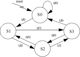
1. Design a circuit (with input x and output z) that implements the above state diagram and uses one-hot encoding for the state assignment. Assume that the only available components are D flipflops (with both Q and Q outputs) and 2-to-1 multiplexers. Make sure to use the minimum number of multiplexers. (10 points)
2. Write a verilog model for a D flip-flop (with both Q and Q outputs). (3 points)
3. Write a verilog model for a 2-to-1 multiplexer. (2 points)
4. Write a verilog model of your design in part 1 using the components described in parts 2 and 3. (10 points)
3. COMBINATIONAL ARITHMETIC CIRCUITS (15 + 10 = 25 POINTS)
Consider a combinational circuit that computes the following three arithmetic functions:
X = A3 Y = A4 Z = A4 – 1
Let us assume that A is an n-bit 2’s complement signed number and the outputs (X, Y, Z) are 2’s complement signed numbers.
1. What is the minimum number of bits needed (in terms of n) for each of the outputs X, Y, and Z?
2. Write a verilog model for the above circuit for the case of n = 4.
The range for a signed n-bit number A is: .
The range for X is . Hence . This is the same as
. So, 3n - 2 bits is sufficient to hold X without overflow.
The range for Y is . Hence . This is the same as
and . So, 4n - 2 bits is sufficient to hold Y without overflow.
Since , then . Hence, and
So, 4n - 3 bits is sufficient to hold Z without overflow.
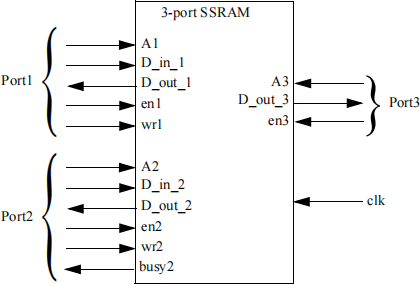
4. MULTIPLE-PORT MEMORY (25 POINTS)
Consider the 3-port SRAM shown below. The SRAM has two read/write ports and one read- only port. All read operations of this SRAM are combinational (asynchronous). The output signal busy2 is set to 1 when the write operation at port2 cannot proceed due to a concurrent write at the same address from port1. Write a complete Verilog model of the SRAM. Your model should be able to handle any special cases that may arise when using the SRAM.
5. SEQUENTIAL ARITHMETIC CIRCUITS (25 POINTS)
This problem involves the design of a sequential circuit that finds the square root of an 8-bit unsigned binary number N using the method of subtracting out odd integers. To find the square root of N, we subtract 1, then 3, then 5, etc., until we can no longer subtract without the result going negative. The number of times we subtract is equal to the square root of N. For example, to find square root of 27 we do the following:
Subtraction #1: 27 – 1 = 236
Subtraction #2: 26 – 3 = 23
Subtraction #3: 23 – 5 = 18
Subtraction #4: 18 – 7 = 11
Subtraction #5: 11 – 9 = 2
Cannot subtract: 2 – 11
Since we subtracted 5 times, then the square root of 27 is 5.
Write a Verilog model that finds the square root of an 8-bit unsigned integer using the above method. Your model should have three inputs: the input number N, a signal input_ready that is set to 1 when the input number N is available, and a clock signal clk. It is safe to assume that once input_ready is set to 1, it will remain 1 during the process of computing the square root. Your model should have two outputs: the square root S of the number N and the output_ready output that is set to 1 when the square root S is computed.
