关键词 > ECE3561
ECE 3561 Project 2: Using VHDL to Design a Simple Sequential Machine
发布时间:2024-06-13
Hello, dear friend, you can consult us at any time if you have any questions, add WeChat: daixieit
ECE 3561
Project 2: Using VHDL to Design a Simple Sequential Machine
In this project, you will use VHDL to design the circuit in Project 1 that models a simple sequential machine with two T flip-flops. In particular, you will use VHDL in the design in place of a schematic. As necessary, review the steps in the previous Xilinx projects to create a new project, generate a vhdl bench, and perform functional simulation. Name your new project 3561Proj2 and your VHDL program sequential.vhd.
Write the VHDL Program
Use the New Source Wizard (Project → New Source → VHDL Module) to
create the “skeleton” VHDL program. Specify the inputs as INPUT, CLR, and CLK and the outputs as Q0, Q1, and RCO, as illustrated in Figure 1. Note that CLR is to be used in this project, instead of PRE, to clear the flip-flops (synchronously) when active.
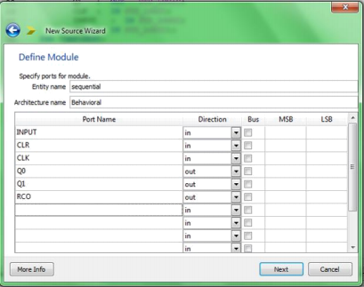
Figure 1. Using VHDL Module
In the ISE Text Editor, the ports are already declared in the VHDL file, and some of the basic program structure is already in place. Keywords are displayed in blue, data types in red, comments in green, and values in black. This color-coding enhances readability and recognition of typographical errors.
Use the Language Templates (Edit → Language Templates) to provide you with the basic VHDL code to construct the two T flip-flops in the sequential machine. (Note that a T flip-flop is a J-K flip-flop with the J-K inputs tied together.) Add two processes to the architecture of your “skeleton” VHDL code by using the T flip-flop with positive- edge triggering and with a synchronous active high reset and clock enable (Language Templates window: expand the selection of VHDL, Synthesis Constructs, Coding Examples, Flip Flops, T Flip Flop, Posedge, and w/ Synchronous Active High Reset and CE) for each flip-flop in the design.
Update the templates for the flip-flops in your program to use the signal names
used in the design. Also, note that you will need to change the Q0 and Q1 ports from “out” to “buffer” so that they can be used internally in the circuit as well. An alternative approach would be to define and use new signals, for instance IQ0 and IQ1, for the internal versions of Q0 and Q1.
To complete the design, add the code to generate the flip-flop excitations (CE0 and CE1) and output (RCO).
Next, model the CLK signal using the technique similar to that for Project 1 for Behavioral Simulation. Like in project 1, set INPUT signal to logic 1 at 1150 ns. (Feel free to copy the block code for modeling the CLK signal from project 1, with necessary modification.) In addition, pulse CLR to a 1 for a single clock period at the beginning of the simulation. Otherwise, the flip-flop outputs would remain undefined.
Once your program is written, save it and check it for syntax errors. (Processes window: expand the selection of ISim Simulator, and double click on Behavioral Check Syntax.)
Functional Simulation and Analysis
Run the ISim Simulator to produce a behavioral simulation of the design. (Processes window: expand ISim Simulator and double click on Behavioral Check Syntax.) Run the simulator for 2500 ns. (Processes window: right click on Simulate Behavioral Model and select Properties to change the Simulation Run Time.)
Verify that your VHDL program implements a 2-bit up-down counter with a synchronous clear and ripple-carry output. Provide a state diagram of the circuit. Keep the states in numeric (non-symbolic) form, and include the INPUT and CLR inputs and the RCO output in the state diagram.
Report
The report should be typed. Be sure to include:
• Title page including course number, project number, your name. The content should start on a separate page.
• A printout of your VHDL program (sequential.vhd). Include your name in the comments in the beginning of the program. Provide comments defining all internal signals that are used.
• The trace output (waveform) for the simulation.
• The state diagram for the sequential circuit with the format clearly given.
