关键词 > EEE112
EEE112 Integrated Electronics and Design 2024
发布时间:2024-05-17
Hello, dear friend, you can consult us at any time if you have any questions, add WeChat: daixieit
EEE112 Integrated Electronics and Design
NMOS IC Design Project (Version 2024)
Assessment Weighting
This assessment counts for 20% of the module.
Aims
This project aims to provide students with an experience of designing a simple integrated circuit at the silicon layout level, as well as offering an insight into the manufacturing process flow.
Learning Outcomes
On completion of this project you should be able to:
1. Understand the manufacturing processes involved in fabricating silicon-based devices.
2. Understand the design process and constraints involved in developing IC.
3. Produce layout and mask designs to scale of an NMOSFET logic circuit.
4. Produce an engineering style report.
Design Task
The objective of this assignment is to design the simple logic circuit shown in Figure 1.
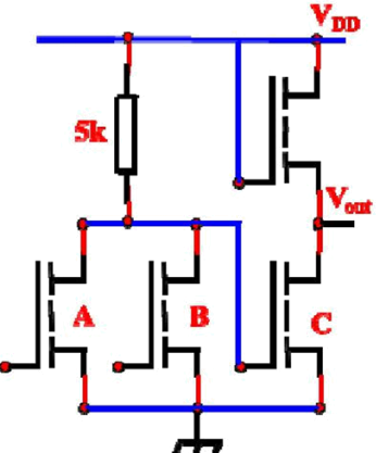
Fig. 1 Simple Logic Circuit
Task 1: What is the logic function of simple logic circuit in Fig. 1?
Task 2: What is the aspect ratio (W/L) for all the NMOSFETs in the circuit (total 4 NMOSFETs)? Please note that the VOUT is assumed to be 0.1V, 0.05V and 0.01V respectively. Please calculate the aspect ratio (W/L) for all the NMOSFETs under different VOUT (0.1V, 0.05V and 0.01V).
The process parameters for the design are listed in Table 1.
Table 1: Process Parameters
|
Normalized Device Constant β0 |
1.8x10⁻⁴ A/V2 |
|
Threshold Voltage VT |
0.7 V |
|
Supply Voltage VDD |
10 V |
|
High Input Voltages (A and B) VIN |
V DD |
|
Low Input Voltages (A and B) VIN |
0 V |
|
Sheet Resistance RS |
200 Ω/□ |
Task 3: 4-mask process is applied for the manufacturing of the NMOSFET. It is required to provide the process flow from step one till the last step. Each step shall have its top view and cross-section view. Please take NMOSFET C as an example (W/L ratio upon VOUT=0.05V).
Task 4 (Extra): If we use the TSMC 5nm technology, 2λ (feature size) is 5nm. You are encouraged to produce a full circuit design layout (full layout) to scale together with the necessary masks to form each layer (from mask 1 to mask 4), by considering the MOSIS design rules (see the last page), and your knowledge from the lectures. (W/L ratio upon VOUT=0.05 V)
You are highly appreciated minimize the full layout as compact and small as possible, following the MOSIS design rules.
Assignment Output and Grading Information
It is required to write a short formal report (no more than 40 pages in total). The report will be graded against the requirements are set out below:
1. Report format: cover page, contents, abstract, introduction, main body, conclusion, references.
2. Main body 1 (Task 1): What is the logic function of simple logic circuit in Fig. 1?
Detailed analysis should be given together with truth table of the simple logic circuit.
3. Main body 2 (Task 2): What is the aspect ratio (W/L) for all the NMOSFETs in the circuit (total 4 NMOSFETs)? Please note that the VOUT is assumed to be 0.1V, 0.05V and 0.01V respectively. Please calculate the aspect ratio (W/L) for all the NMOSFETs under different VOUT (0.1V, 0.05V and 0.01V).
The process parameters for the design are listed in Table 1.
Table 1: Process Parameters
|
Normalized Device Constant β0 |
1.8x10⁻⁴ A/V2 |
|
Threshold Voltage VT |
0.7 V |
|
Supply Voltage VDD |
10 V |
|
High Input Voltages (A and B) VIN |
V DD |
|
Low Input Voltages (A and B) VIN |
0 V |
|
MOSFET Load Resistance RL |
5 kΩ |
|
Sheet Resistance RS |
200 Ω/□ |
Please provide the detailed analysis for the calculation. It is also important to identify which mode (linear or saturation)for all the NMOSFETs in the circuit (total 4 NMOSFETs).
4. Main body 3 (Task 3): 4-mask process is applied for the manufacturing of the
NMOSFET. It is required to provide the process flow from step one till the last step. Each step shall have its top view and cross-section view. Please take NMOSFET C as an example (W/L ratio upon VOUT=0.05 V).
Clearer and detailed discussion for all the steps are required in this section, together its top view and cross-section view.
5. Main body 4 (Extra): If we use the TSMC 5nm technology, 2λ (feature size) is 5nm. You are encouraged to produce a full circuit design layout (full layout) to scale together with the necessary masks to form each layer (from mask 1 to mask 4), by considering the MOSIS design rules (see the last page), and your knowledge from the lectures (W/L ratio upon VOUT=0.05 V).
You are suggested to use handwrite or software for the full layout and four masks. Full layout means the final layout merging four masks together. For handwrite, either photo or scan into the report is acceptable. For software,figure capture is acceptable.
Please identify the related MOSIS design rules in your design. (unit: nm)
Mask information is listed as follow:
1. Mask 1: Active layer
2. Mask 2: Poly-Si layer
3. Mask 3: Contact layer
4. Mask 4: Metal layer
5. Full layout: Overlay of all the masks (merging four masks together)
Academic Misconduct
Students should be aware that when submitting assessed work that the work is their own and that it fully acknowledges the work and opinions of others. For further clarification students should read the latest version of the XJTLU Code of Conduct. These can be found on the university webpages.
Assignment Submission and Deadline
Please submit your completed design assignment report directly to the assignment on Learning Mall no later than:
Late submission shall follow university policy available on the university website.
Note: Please make sure you attach the university assignment cover sheet to your report.
MOSIS Layout Design Rules
Active Area Rules
R1 Minimum Active area Width 3λ
R2 Minimum Active area Spacing 3λ
Poly-Silicon Rules
R3 Minimum Poly Width 2λ
R4 Minimum Poly Spacing 2λ
R5 Minimum Gate extension of Poly over Active 2λ
R6 Minimum Poly-Active Edge Spacing λ
(Poly Outside of Active area)
R7 Minimum Poly-Active Edge Spacing 3λ
(Poly Inside of Active area)
Metal Rules
R8 Minimum Metal Width 3λ
R9 Minimum Metal Spacing 3λ
Contact Rules
R10 Poly Contact size 2λ
R11 Minimum Poly Contact Spacing 2λ
R12 Minimum Poly Contact to Poly Edge Spacing λ
R13 Minimum Poly Contact to Metal Edge Spacing λ
R14 Minimum Poly Contact to Active Edge Spacing 3λ
R15 Active Contact size 2λ
R16 Minimum Active Contact Spacing 2λ
(On the same Active region)
R17 Minimum Active Contact to Active Edge Spacing λ
R18 Minimum Active Contact to Metal Edge Spacing λ
R19 Minimum Active Contact to Poly Edge Spacing 2λ
R20 Minimum Active Contact Spacing 6λ
(On different Active regions)
Supply Rail Metal
R21 VDD >3λ
R22 Ground >3λ
Resistor Rules
R23 Minimum resistor width 2λ
