关键词 > EENGM2510
EENGM2510 ADVANCED MOBILE RADIO TECHNIQUES 2019
发布时间:2024-05-16
Hello, dear friend, you can consult us at any time if you have any questions, add WeChat: daixieit
EENGM2510
ADVANCED MOBILE RADIO TECHNIQUES
MAY/JUNE 2019
Q1 Discuss the advantages and disadvantages of each of the following approaches to equalisation. Your answers should make reference to modulation scheme, channel memory, equaliser performance, the computational complexity of implementing the equaliser and the complexity of calculating the equaliser coefficients.
Note that the number of marks allocated for parts (a) and (b) are less than for (c) and (d) and therefore more discussion is required for the latter two parts.
(a) Time Domain Equalisation where the equaliser is a Linear Transverse Equaliser (LTE) and the equaliser coefficients are adapted according to a Least Mean Squares (LMS) algorithm. (2 marks)
(b) Time Domain Equalisation where the equaliser is a Linear Transverse Equaliser (LTE) wherein the equaliser coefficients are adapted according to a Minimum Mean Square Error (MMSE) algorithm. (2 marks)
(c) Time Domain Equalisation where equalisation is implemented in the form of Maximum Likelihood Sequence Estimation (MLSE) via the Viterbi Algorithm. (3 marks)
(d) Frequency Domain Equalisation where the equaliser is implemented in the receiver of an Orthogonal Frequency Division Multiplex (OFDM) system. (3 marks)
Q2 (a) Briefly describe the signal or waveform signal processing tasks in a generic Spread Spectrum communication system. Explain how this can be extended to provide Multiple Access. (2 marks)
(b) Sketch a block diagram for the maximal length sequence generator described by the following polynomial. Clearly label the functional blocks, inputs and outputs.
1 + x3 + x5
If the shift registers are pre-loaded with a logic zero state, explain what happens. (3 marks)
(c) With the aid of a block diagram, explain the key sub-system components of an Adaptive Antenna Array designed to optimise signal reception in the presence of multiple spatially separated interferences sources. (3 marks)
(d) Explain how a communication system employing antenna arrays at either ends of a wireless link, (ie Multiple-Input Multiple- Output (MIMO)) can enhance the Spectrum Efficiency when compared to use of single antennas. (2 marks)
Q3 Consider two different communication systems requiring the design of suitable equalisers.
System ‘A’:
. Has symbol rate, fs = 20MHz
. Uses a range of modulation schemes up to and including 64-QAM
. Operates in a channel wherein the expected conditions are:
RMS Delay Spread τRMS = 100ns
Excess Delay Spread τMax = 800ns RMS Doppler Spread FD = 200Hz
A Power Delay Profile wherein the power of each tap decreases as the delay increases.
System ‘B’:
. Has symbol rate, fs = 10MHz
. Uses only BPSK symbol modulation
. Operates in a channel wherein the expected conditions are:
RMS Delay Spread τRMS = 10ns
Excess Delay Spread τMax = 400ns RMS Doppler Spread FD = 800Hz
A Power Delay Profile wherein the power of each tap decreases as the delay increases.
(a) For each of systems ‘A’, and ‘B’, calculate the number of taps required if a Time Domain Decision Feedback Equaliser is implemented in the receiver. (2 marks)
(b) For each of systems ‘A’ and ‘B’, calculate the number of states in a MLSE equaliser if that is implemented in the receiver. (2 marks)
(c) For each of systems ‘A’ and ‘B’, if OFDM modulation is used, suggest a suitable FFT size and Guard Interval length. (4 marks)
(d) If OFDM modulation is used determine the number of taps in the frequency domain equaliser for each system and compare the rate at which the complex multiplications in the equaliser must be executed to those in (a). (2 marks)
(e) Discuss the merits of choosing Time Domain Decision Feedback Equalisation, MLSE equalisation or OFDM Frequency Domain equalisation for each of systems ‘A’ and ‘B’ and determine which you believe to be the superior option(s). Justify your decisions. (4 marks)
(f) Consider now the design of system ‘C’ which is the same as system ‘B’ except that the channel Power Delay Profile is such that the power of each tap ‘increases’ as the delay increases. How does this change your options for equalisation? Justify your choices. Note that no further calculations are required. (2 marks)
(g) Consider now the design of system ‘D’. If system ‘D’ is similar to system ‘A’ but required to achieve a low peak-to-mean power ratio in its transmitted signal, what changes could be made to the modulation and equalisation methods discussed above in order to facilitate lower peak-to-mean power ratios? Discuss the cost of any changes you propose. (4 marks)
Q4 (a) (i) For a Direct Sequence Spread Spectrum (DS-SS) application, explain why a Rake receiver can improve link performance in a dynamically fading environment. (1 mark)
(ii) Sketch a block diagram of a Rake Receiver. Clearly label each functional block and fully describe its operation, including the different signal combining options. (3 marks)
(iii) When used with a 5MChip/s waveform, what inter-stage time delay should be used? What physical path length does this correspond to? (1 mark)
(b) (i) Explain why Power Control is necessary in a multi-user DS-SS system. What is the likely impact on Network Capacity if power control errors occur? (1 mark)
(ii) Carefully explain how Power Control could be implemented for a Frequency Division Duplex mobile network using DS-SS access. (1 mark)
(iii) Sketch a graph showing received power from a moving mobile terminal as seen at a DS-SS basestation for non-power controlled and power controlled waveforms. Describe what happens if the terminal is moving at a rate faster than the update rate. How could this effect be addressed in the waveform or protocol design? (2 marks)
(c) (i) Derive a mathematical model for a Multiple-Input Multiple-Output MIMO wireless system for the case of conventional MIMO (ie NOT Massive MIMO). (4 marks)
(ii) Explain how Spatial Multiplexing and Space-Time Block Coding can be applied to a MIMO enabled wireless system. Under what channel conditions should these techniques be applied? (1 mark)
(iii) Sketch a graph indicating the likely variation in the Eigenvalue channel gains for a 4 x 4 MIMO system in a non-line of sight environment. How and why should Water Filling be applied? (2 marks)
(d) (i) List 2 benefits of applying Massive MIMO to wireless communications and briefly justify your reasons. (1 mark)
(ii) Briefly explain why TDD based air interfaces are well suited to Massive MIMO system deployments. (1 mark)
(iii) Figure Q 4 shows the HHH matrix obtained from a field trial of a 12 user massive MIMO system for varying number of antennas at the basestation as shown in the figure. What physical parameter does HHH represent? Using this data, explain the benefits from increasing the number of antennas from 32 to 64 and then to 112.
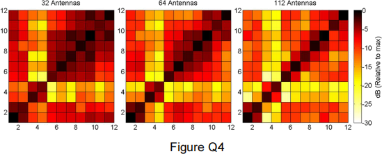 (1 mark)
(iv) In the context of Downlink transmission in Massive MIMO, explain what is meant by the term ‘interstream interference’ and explain the likely causes of this problem. (1 mark)
