关键词 > MECH265001
MECH265001 Mechatronics and Measurement Systems 2022
发布时间:2024-05-16
Hello, dear friend, you can consult us at any time if you have any questions, add WeChat: daixieit
MECH265001
Mechatronics and Measurement Systems
May/June 2022
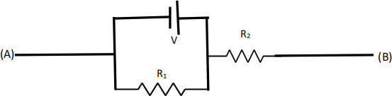
Q1.
Using only the following two equations:
derive the equivalent resistor between (A) and (B) of the circuit shown in Figure Q1, where the voltage source V has no internal resistance. Show all derivation steps. [5 Marks]
Q2.
Using one 2 [kΩ] resistor and two 10 [kΩ] resistors, construct the inverting amplifier to achieve 2.5-times amplification of the input voltage. Draw the circuit with the resistors and the op-amp. Show that the circuit provides 2.5-times amplification of input voltage. [5 Marks]
Q3.
The DC motor equation is given by
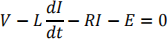
where V is the input voltage to the motor, L is the motor inductance, R is the motor internal resistance, I is the electrical current, and E is the back EMF.
The motor is connected to a mobile robot with a wheel, and the dynamics is given by
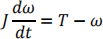
where J is the wheel moment of inertia, ω is the angular velocity, and T is the motor torque.
Assume that the gear ratio between the motor and the wheel is 1:1.
a) Obtain the transfer function between the angular velocity as the output and the motor input voltage as the input of the transfer function. Do not assume any steady-state. [10 Marks]
b) Let L =0.5 [H], R=0.1 [Ω], the back EMF or the torque constant is equal to 0.01
[V/(rad/s)], and the wheel moment of inertia is 2 [kg m2]. The following input voltage is applied to the motor for a sufficiently long period of time:
v(t) = sin(0.1 t)
Calculate the wheel angular velocity in terms of a function of time. Show all calculation steps [10 Marks]
c) Design a proportional controller to achieve a desired constant angular velocity, 10
[rad/s], for the DC motor transfer function obtained in b). Draw a block diagram showing connections between the motor, the controller, and the desired angular velocity. And, show that it is practically impossible to make the steady-state error equal to zero using the proportional controller. [10 Marks]
Q4.
Using the following components
- DC Motor
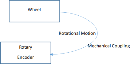
- Wheel for autonomous mobile robots
- H-bridge
- Voltage source
- PWM modulator
- Rotary encoder
- Micro-controller
complete the following functional block diagram to design a wheel balanced inverted pendulum. Indicate clearly input and output signals between components in the block diagram.
 [10 Marks]
Q5.
The mass M is falling at a constant velocity. The pressure P in the hydraulic cylinder is 60 bar, and the volume flow rate Q is 5×10⁻⁴ m3/s. The cylinder has a bore of 35 mm and a piston rod diameter is 20 mm.
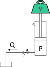
• Calculate the velocity at which the mass is dropping and the value of M.
• Calculate the power dissipated through the restrictor (in Watt) and the restrictor constant Kr. [10 Marks]
Q6.
Two strips of PZT are bonded to form a bimorph actuator shown in the figure below. The bimorph has a small mass at the free end.
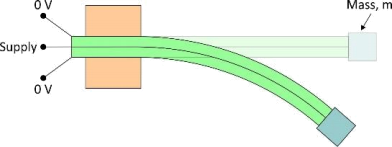
Each actuator has the following specifications:
|
Dimensions: |
length = 50 mm, width = 5 mm, thickness = 0.5 mm |
|
PZT charge constant: |
d13 = - 133×10- 12 m/V, d33 = 500×10- 12 m/V |
|
PZT Young’s Modulus: |
E = 70×109 N/m2 |
|
Available voltage source: |
±200 V |
(Assume ideal actuator characteristics.)
• With no electrical connections to the bimorph, the mass vibrates freely at 63.66 Hz when disturbed. What is the value of the mass, m?
• By applying a voltage to the supply as shown, the mass can be raised and lowered. Find the full range of motion available.
• Find the voltage required to maintain zero deflection with the weight added. [20 Marks]
Q7.
Design a pneumatic circuit diagram using CETOP symbols to operate two double acting cylinders in the repeating sequence 1A+ 2A+ 2A- 1A-. Cylinder 2A must remain at full extension until a delay of T has elapsed and contact pressure of P has been achieved. [20 marks]
