关键词 > MECH265001
MECH265001 Mechatronics and Measurement Systems 2021
发布时间:2024-05-16
Hello, dear friend, you can consult us at any time if you have any questions, add WeChat: daixieit
MECH265001
Mechatronics and Measurement Systems
May/June 2021
Section A
Q1.
a) Draw logic gate diagram that achieves the XOR relationship using the three basic logic gates, AND, OR, NOT. [3 Marks]
b) For constructing the non-inverting amplifier to gain of 11, explain what would be the possible issues when 10Ω and 100Ω resistors are used. [3 Marks]
c) What is the main advantage of the grey code for rotary encoder sensors compared to the binary code? [1 Marks]
d) The high-level output voltage of a PWM (Pulse-Width Modulator) is equal to 2V, the low-level output voltage is 0V, and the period is equal to 0.1 seconds. To generate 0.25V equivalent using the PWM, how long the voltage must be equal to 2V during a single period? [3 Marks]
Q2.
Figure Q2 shows the signal processing circuit for the strain gauge to measure force. The strain gauge is attached to a robot arm. The strain gauge is represented by the varying resistor R2 in the figure.
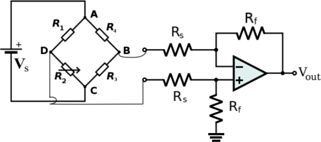
Figure Q2. Strain Gauge and Signal Processing
The resistors and the supplied voltage in the figure are
R1 = 59Ω , R3 = 50Ω , R4 =200Ω , RS =1kΩ, Rf = 10kΩ , ![]() s = 2V
s = 2V
The specifications of the strain gauge are as follows:
- Nominal resistance: 125Ω
- Gauge Factor: 2
The robot arm is lifting an object and the voltage, Vout measured to be equal to 9.505V.
a) Calculate the resistor change in the strain gauge during the lifting [15 Marks]
b) Calculate the strain occurred in the robot arm during the lifting [3 Marks]
c) Provide formula and explain how to calculate the force applied to the robot arm [2 Marks]
Q3.
The following set of three differential equations is a simplified description of aircraft pitch dynamics:
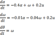
where a is the angle between the aircraft velocity and the air flow velocity, ω is the pitch angular velocity, θ is the pitch angle, u is the control input by control surface, and t is the time.
a) Obtain the transfer function, G(s), in the following equation:
Θ(s) = G(s)U(s)
where s is the variable in the Laplace transform, Θ(s) is the Laplace transform of θ(t), and U(s) is the Laplace transform of u(t). [10 marks]
b) To identify the characteristics of the transfer function, G(s), the control input is set to the sinusoidal function as follows:
u(t) = asin(b × t),
where a and b are constants to be chosen. The pitch angle, θ, is to be measured by a sensor.
Explain why this experiment would fail to identify the characteristics of the transfer function, G(s). [5 marks]
c) The state-feedback controller is designed as follows:
u(t) = −0.1a − 0.2ω − 0.3θ
Obtain the characteristic equation of the closed-loop system with the controller, and evaluate the stability of the closed-loop system. [5 marks]
Section B
Q4.
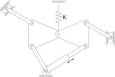
Find the number of degrees of freedom of the mechanism given below.
(Number of links = 1 mark, number of half joints = 1 mark, number of full joints = 1 mark, number of degrees of freedom = 2 marks) [5 marks]
Q5.
The following schematic shows a mechatronic application, where a 1 Kg mass must be accelerated to reach steady state velocity of 0.2 m/s using a PZT based hydraulic pump. To achieve this, a voltage amplifier is designed to provide sinusoidal voltage to the PZT stack with a frequency of 20 kHz. Calculate the amplitude of voltage required for this application at the current position of the directional control valve, as shown in the circuit diagram. (Assume incompressible fluid for this application.)
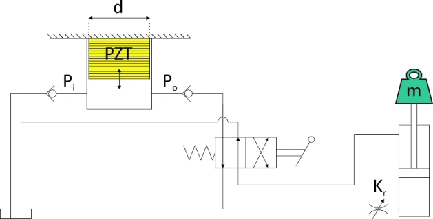
System parameters:
. Kr = 4.5×10⁻⁷ m4.s- 1.N-0.5
. Cylinder’s piston area = 2×10⁻⁴ m2
. Cylinder’s rod area = 0.5×10⁻⁴ m2
. PZT stack: 40 cylindrical disks, each with diameter (d) = 20 mm and thickness = 0.3
mm
. PZT charge constant: d13 = - 133×10- 12 m/V, d33 = 500×10- 12 m/V
. PZT Young’s Modulus: E = 70×109 N/m2 [25 marks]
Q6.
Design a pneumatic circuit diagram to operate three double acting cylinders in the repeating sequence 1A+ 2A+ 2A- 3A+ 1A- 3A- with a contact pressure controller for cylinder 2A extension.
(Valves circuit configurations per cylinder = 3 marks, Pressure controller = 3 marks, use of correct circuitry = 3 marks, functional circuit = 3 marks, labelling = 2 marks) [20 marks]
