关键词 > ECS700P/U
ECS700P/U – Mechatronics (2023)
发布时间:2023-12-14
Hello, dear friend, you can consult us at any time if you have any questions, add WeChat: daixieit
ECS700P/U - Mechatronics (2023)
Coursework 2: Modelling and control of an inverted pendulum
(developed by Dr Ildar Farkhatdinov, questions:i.farkhatdinov@qmul.ac.ukor QM+ forum)
. This coursework contributes to 50% of the total mark for the module. Max mark is 50.
. You will need access to Matlab Simulink to complete the coursework.
Aims:
- to learn functionality, implementation and dynamics of sensing, actuation and control
- to learn Matlab functionality to model mechatronicsystems
Your task:
Consider a planar 1-link robot show in Figure 1 (inverted pendulum). The link (length L) with amass mis driven with a DC motor integrated with a planetary gear with speed reduction rate n and inertia Jt. A PID controller implemented with analogue electronic devices and an H-bridge generating PWM signals are used to control the link angular orientation q. The robot is affected by gravitational acceleration g. Your task is to model this system.
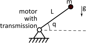
Figure 1. Single link inverted pendulum.
Initially an optical angular position encoder was used to measure q, but due to a technical fault the sensor had to be replaced by a gyroscope (gyrometer) that provided a biased and noisy measurement of the angular velocity. The gyroscope measures the rate of change of q which is then used to control the DC-motor to change the orientation to a required reference angle qref. The controller (implemented with proportional-integral-derivative regulator PID) should change the actual orientation to a desired angle qref.
In this coursework, you need to implement and analyse a model for the control of this robot. A simplified diagram of the model is shown in Figure 2.
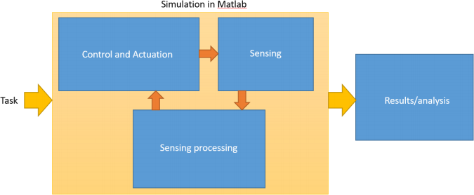
Figure 2. General schematic view of the model and coursework task,
A more detailed structure of the sub-systems is shown in Figure 3. Your model will be composed of a gyroscope (with gain 5 and time constant 100 ms), electrical filters (RC or RL), bias compensator and integrator, PID controller, pulse- width-modulator (PWM), H-bridge and a DC motor with a planetary gear transmission.
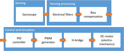
Figure 3. Control/actuation and sensing/processing subsystems.
Your task is to implement this system in Matlab (Simulink), run the simulation and write a technical report describing your model. Detailed subtasks are described in the following sections. Each sub-task has two or three level difficulties: A – simple; B – normal; C – advanced. The maximal mark you can get for each subtask depends on the level of difficulty your select (how detailed is your model). You are required to implement one level of difficulty per subtask. You can skip any subtask, and test the overall system performance without the skipped sub-system. For example, you can implement the system without filters (use direct sensors’ measurements for control).
Your robot should be stabilised at a certain angle (for example, 40 degrees) from a non-zero initial condition (for example (-5 degrees). Your turbine control should be fast enough (for example, settling time <2 s and max. overshooting 20%). Use your own values for initial/reference angles and performance metrics.
You need to define your parameter values for modelling sensors, actuators, noise, filters. Please, use existing datasheets where possible. All used datasheets/online materials should be cited in the report. The values of defined parameters should be physically meaningful.
Robot parameters: m=0.x+0.2 kg, L=0.5+0.xm, n=x+1, Jt=0.0xkgm2 where x is the last digit of you student number.
Detailed subtasks description*:
1. DC-motor, planetary gear (inertia and gear ratio) and platform models.
You can model this sub-system with:
A. Transfer function blocks including only mechanical dynamics and ignoring electrical dynamics (Simulink ordinary blocks)
B. Math/derivative/integral elements (Simulink ordinary blocks)
C. Electrical/mechanical blocks (Simscape blocks combined with Simulink blocks)
Possible DC-motor datasheet: Maxon Motor 353294 (or similar).
2. PWM generator, H-bridge and PID controller.
You can model this sub-system with:
A. Skip modelling and use math gain 1 instead of PWM and H-bridge. Ready-made PID block (Simulink extras).
B. Only model PWM block with Simscape PWM block. PID implemented with Math/derivative/integral elements (Simulink ordinary blocks).
C. Electrical/power blocks (Simscape blocks combined with Simulink blocks). Operational amplifier block with electrical elements used in feedback (Simscape blocks combined with Simulink blocks).
3. Gyroscope.
You can model this sub-system with:
A. Transfer function with sensory noise, no bias
B. Transfer function with sensory noise including bias
C. State-space model with sensory noise and bias
Possible sensor parameters: time constant 100 ms, gain 5.
Possible noise parameters: random, mean 0.03 rad/s, standard deviation 0.05 rad/s, normally distributed.
Important: the gyroscope’s model input should be the angular velocity of the robot’slink (since the gyroscope is fixed to link)
4. Electrical filter to reduce noise
You can model this sub-system with:
A. Transfer functions (low-pass with relevant cut-off)
B. Transfer functions, band pass filter (for example, low frequency cut-off 1 Hz, high-frequency 0.001 Hz, or similar)
C. Electrical circuit blocks (Simscape), band pass filter (see B for parameters)
5. Adding optical encoder and sensor fusion
Consider that additional optical encode was added to the robot attached to the output shaft of the planetary gear transmission with resolution of 2 degrees. Test and demonstrate the feedback control:
A. Use integrator block and with simple math operators for gyroscope bias compensation (+/i/* or similar). B. Use new optical encoder instead of the gyroscope and compare the results with A.
C. Propose and implement a sensor fusion approach that uses gyroscope and optical encoder measurements for feedback control (for example using weighted or simple average or other techniques).
6. Modelling nonlinearity in planetary gear system
A. Add viscous friction model to the planetary gear.
B. Same as A and add modelling of a dry friction to the planetary gear model.
C. Same as B and add modelling of backlash to the planetary gear mode.
7. Overall system testing.
A. Demonstrate that stabilisation of the platform works.
B. Demonstrate performance of the system with different PID control gains.
C. Demonstrate performance of the system with different PID control gains and with/without bias compensation.
Marking. For each successfully completed subtask (modelling works and explained in the report with description, input/output plots) you will get:
+(1…2) marks for correct implementation difficulty A
+(3…4) marks for correct implementation difficulty B
+(5…6) marks for correct implementation difficulty C
The above will be assessed based on the information provided in the report, video and Simulink files.
See subtasks description for specific marks awarded for successfully completed tasks based on the complexity.
Additional marks (up to):
+2: appropriate formatting, with figure references, citations, sections, subsections
+2: for not using screenshots for the plots from Simulink (instead save the data to Matlab workspace and use plot function)
+8: marks for video recording describing the total model and demonstrating its operation
Note, that the final maximal mark for the coursework is 50.
Submission (compulsory):
- Report (PDF)
- Matlab Simulink model file (SINGLE model file)
- Screen capture video recording with your voice explaining your Matlab model/code (up to 2-3 minutes) Proposed report structure (recommended 5-7 pages, Arial 11 pt, 2 cm margins):
0. Title page (with QMUL logo, module information, student name/number/email)
1. Summary/Introduction to the overall system
2. Subsystem
3. Subsystem
4. Subsystem
5. Overall system modelling demonstration (subtask 7)
References
*subsystems description can be 3-7 sentences long.
Simulink model file(s):
- Organise the model in systems/subsystems
- Add relevant labels/comments to the Simulink model
- See Matlab Simulink help, online tutorials from Mathworks
