关键词 > COMP4620/8620
COMP4620/8620 – Advanced Topics in AI Semester-2 2023 – Assignment 1
发布时间:2023-09-05
Hello, dear friend, you can consult us at any time if you have any questions, add WeChat: daixieit
COMP4620/8620 – Advanced Topics in AI
Decision-making under Uncertainty in Robotics
Semester-2 2023 – Assignment 1
Due date: Monday, 4 September 2023 23:59 Canberra time
Update 29/08/23:
• No changes in the text, just reposition the picture to look nicer :)
Update 22/08/23:
• In each primitive step, the chair cannot move more than 0.10 rad 0.1 0 .
• The time limit used will be CPU time. The time limit for the examples in the accompanying supporting codes are: 4 seconds for the no gripper example and 10 seconds for the example with gripper.
Update 14/08/23:
• Replace all hypen (‘-’) in class/file/folder names with underscore (‘ ’)
Notes:
1. This is an individual assignment.
2. This assignment consists of two parts: Programming and Report. The maximum total mark is 100 points, with a maximum of 60 points for the Programming component and a maximum of 40 points for the Report component.
3. Submission Instruction:
(a) You must write your program in Java. Supporting code (for checking the validity of a configuration) is provided.
(b) Your main program should be placed in a file named a1 [courseCode] [UID].java.
(c) Your program should compile from command prompt (e.g., using ant) and generate a file that can be run from command prompt as:
> java -jar a1 [courseCode] [UID].jar inputFileName outputFileName
OR
> java a1 [courseCode] [UID] inputFileName outputFileName
[courseCode] must be replaced with 4620 or 8620, depending on which class you are enrolled in.
[UID] must be replaced with your ANU ID.
(d) The report should be in .pdf format and named a1 [courseCode] [UID].pdf.
(e) The report and all the source codes necessary to compile your program should be placed inside a folder named a1 [courseCode] [UID]. Please submit only source codes (i.e., remove all object an executable files).
(f) The folder should be zipped under the name a1 [courseCode] [UID].zip and the zip file should be submitted via wattle before the due date.
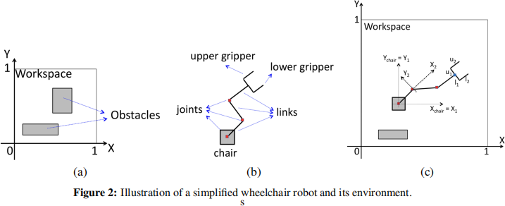
UNA has purchased the hardware for a robotics wheelchair that staff and students in need can use for free. It is essen-tially a wheelchair with a robotics arm and gripper, as il-lustrated in Figure 1. To provide better functionality, UNA is developing the software package to plan the wheelchair robot motion autonomously, given initial and goal config-urations. COMP4620/8620 has been hired to develop the core motion planning component of the software, and this assignment is about developing a simplified prototype of the planner.
Specifically, in this assignment, you need to develop a mo-tion planning method and its implementation for a simplified version of the above wheelchair and analyse its performance. The simplification is detailed below.
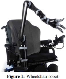
The simplified wheelchair robot operates in a 2D workspace (rather than 3D). In particular, the 2D workspace is a plane, represented as [0, 1] × [0, 1] ⊂ R 2 and is populated by rectangular obstacles. The exact dimension and position of each obstacle in the environment is known prior to execution. Figure 2(a) illustrates an example of this environment.
The wheelchair robot is composed of three parts: The chair (base), a robot arm, and a gripper (illus-trated in Figure 2(b)). The details of each part are:
1. The chair can be thought of as a base for the arm (and gripper) and is a square of size 0.04×0.04 unit2 . The base can only translate. A local coordinate system is attached to this base. The origin of this coordinate system is at the center of the square, while the X and Y axis are parallel to the X and Y axis of the workspace, as illustrated in Figure 2(c).
2. The robot arm forms a chain and consists of J links and J joints, where J is a positive integer. Each link is a line segment attached to a joint. We number the joints and links sequentially (with the index starting at 1), i.e., joint-1 is located at the center of the base, link-1 is a line-segment attached to joint-1, joint-2 lies at the other end of link-1, etc. Each joint is a rotational joint. A local coordinate system is attached to each joint. The origin of this coordinate system is the position of the joint. For joint-1, this coordinate system coincides with the coordinate system of the base. For other joints, the X axis is the line that coincides with the previous link. Each joint is a rotational joint, which means it can only rotate. We define the joint angle of joint-i as the angle between link-i and the X axis of the coordinate system attached to joint-i. The joint angle of each joint is limited to be within [−1500, 1500 ]. Figure 2(c) illustrates the coordinate system of the rotational joints. Each link is of size 0.05 unit length.
3. The gripper consists of 2 L shape segments: upper and lower gripper, as illustrated in Fig-ure 2(c). It is attached to the last link of the arm and has a fixed relative orientation with respect to the last link of the arm. However, the length of the segments can be altered and is defined as (u1, u2) for the upper gripper and as (l1, l2) for the lower gripper, where u1, u2, l1, l2 ∈ [0.03, 0.07].
What your program should do
Given the initial and goal configurations of the wheelchair robot, as well as a map of the environment, your program must find a valid path from the initial to the goal configuration. A valid path means that when the wheelchair robot executes the path, it will satisfy the following requirements:
1. The path consists of primitive steps. In each primitive step, the chair cannot move more than 0.001 unit, each joint angle cannot move more than 0.10 rad 0.1 0 , and the length of a segment in the gripper cannot move more 0.001 unit.
2. The robot will not collide with any of the obstacles in the workspace.
3. The robot will not collide with itself.
4. The entire wheelchair robot must lie inside the workspace.
5. The joint angles for the robot arm and the segment length for the gripper must be inside their respective lower and upper limit as described in the previous section (i.e. [−1500, 1500 ] for the joint angles and [0.03, 0.07] for the segment length).
6. Since a primitive step is very small, it is sufficient to satisfy requirements 2-5 at the beginning and end of each primitive step.
To help you develop the motion planning solution, we provide a supporting program (in Java) to test if a configuration satisfies the above validity requirements.
Your program should take a .txt file containing the problem scenarios as input and output a .txt file containing the resulting path. The input and output should follow the format described in the next section.
Input and Output format
To describe the format of the input file, we first need to describe the format of a configuration.
Format of a configuration. A configuration is represented by n real numbers, where n is the dimension of the C-space. Each number is separated by a white space. The first two numbers are the position of the origin of the chair’s coordinate system in the workspace. If the wheelchair does not have a gripper, the last n − 2 numbers are the joint angles in sequential order (i.e., the third number is the joint angle of joint-1, the fourth number is the joint angle of joint-2, etc.). Each joint angle is defined in radian. If the wheelchair has a gripper, the subsequent n − 6 numbers are the joint angles in sequential order, while the last 4 numbers are the values of u1, u2, l1, l2, respectively.
Input format. The program you develop should accept a .txt file as input. The file contains the type of wheelchair, the initial and goal configurations, and the obstacles position and dimension. The format of the input file is as follows.
1. The file consists of k + 4 lines, where k is the number of obstacles in the environment.
2. The first line is the type of wheelchair robot. There is only two possibilities, i.e., withGripper and noGripper for a wheelchair robot with a gripper and without a gripper, respectively.
3. The second line is the initial configuration.
4. The third line is the goal configuration.
5. The fourth line is the number of obstacles in the environment.
6. Each line in the next k lines represents an obstacle and consists of 4 real numbers. The first two numbers represent the X and Y position of the upper-left vertex of the rectangle, while the last two represent the X and Y position of the lower-right vertex of the rectangle.
Output format. Your program should output the wheelchair robot’s path to a .txt file with the following format.
1. The file consists of m + 2 lines, where m is the number of primitive steps in your path.
2. The first line is the number of line-segments.
3. The second line is the initial configuration.
4. The next m lines are the end configuration of each primitive step.
Examples of the input and output files are in the accompanying supporting program.
Grading for the Programming Part (total points: 60/100)
For marking, we will use 2 different classes of queries:
1. Class-1: The wheelchair robot consists of a chair and an arm.
2. Class-2: The wheelchair robot consists of all components, i.e., a chair, arm, and gripper.
Each class has 3 problem scenarios and queries. The arm in each scenario will have at least 1 joint and 1 link, and at most 10 joints and 10 links.
If you use sampling-based method, we will run your program 5× for each query. Your program is deemed as solving the query within the given time limit if it solves at least 3 out of 5 runs within the given time limit. The details of the grading scheme is provided below.
• Mark = 0: No program is submitted
• 1 ≤ Mark < 10: The program does not compile.
• 10 ≤ Mark < 15: The program compiles but does not run.
• If the program runs, you will receive 15 points plus Total QueryMarks, where each QueryMark will be given as follows:
1. For each query where your program fails to output a valid path within 2× the time limit, you will receive a QueryMark = 1.
2. For each query where your program outputs a valid path but requires a planning time longer than the time limit but under 2× the time limit, you will receive a QueryMark = 3 for class-1 scenario (i.e., no gripper) and a QueryMark = 4.5 for class-2 scenario (i.e., with gripper).
3. For each query where your program outputs a valid path longer than the time limit, you will receive a QueryMark = 6 for class-1 scenario (i.e., no gripper) and a QueryMark = 9 for class-2 scenario (i.e., with gripper).
Report (total points: 40/100)
Your report must contain answers to the following questions:
1. [5 pts] Please define the Configuration Space of the problem.
2. [10 pts] Please explain the motion planning method that you use to solve the problem. You need to include the description of the solution and reasonings for why you choose the particular method and the design choices you made.
3. [12.5 pts] Please provide empirical analysis of your method with respect to the number of links in the arm of the wheelchair robot, for both classes of queries. Please provide the scenario (environment) you use for testing in the report.
4. [12.5 pts] Under what situation will your program fail? Please explain your answer.
Hint on how to get started
The following tasks are provided as hints to get you started.
1. Define the Configuration Space of the problem
2. Identify a suitable motion planning method for solving. If the method you choose to use is sampling-based motion planning, you will need to:
(a) Develop the method for sampling the milestones
(b) Develop the method to insert edges
(c) Develop the method to find a path from the given initial to goal configurations.
3. Evaluate your method. If you use sampling-based method, this evaluation needs to consider the random nature of the method.
