关键词 > CIVE5670M01/CIVE5671M01
CIVE5670M01/CIVE5671M01
发布时间:2023-08-14
Hello, dear friend, you can consult us at any time if you have any questions, add WeChat: daixieit
Module code: CIVE5670M01/CIVE5671M01
Section A Each question is worth 8 marks. Attempt all questions
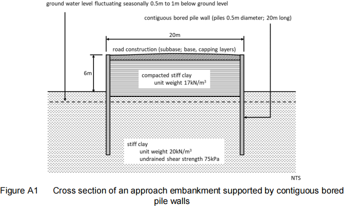
A1. Figure A1 is a cross section of an embankment supported by embedded concrete contiguous bored pile walls. This structure is an approach embankment for a bridge crossing a road. The sequence of construction was as follows:
. Bored reinforced concrete pile wall installed.
. Excavated and remoulded overconsolidated stiff clay compacted in layers between the walls.
. Road construction formed of a granular subbase, base and asphalt surface layer placed on top of the compacted backfill
Sometime after construction it was noted that the walls were no longer vertical; deflection measurements showed that the walls were rotating outwards from below the original ground level. Further, the road surface showed signs of rutting and settlement. The settlement was most obvious at the point at the intersection between the bridge deck and compacted fill.
(a) Explain possible reasons as to why the wall deflected, and the road surface rutted and settled.
(b) What measures could be taken to limit any further movement? [8 marks]
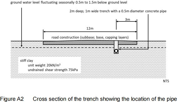
A2. Figure A2 shows a cross section of a trench running parallel to the centre line and beneath a main road. The trench is 2m deep and 1m wide. According to the contractor the trench was built according to the specification; i.e. granular soil was compacted in layers around and above the 0.5m diameter concrete sewer with a 0.5m thick road construction on top of the engineered fill. Determine the maximum load on the pipe due to the backfill. [8 marks]
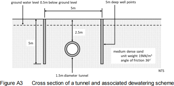
A3. Figure A3 shows the cross section of a proposed 1.5m diameter tunnel in medium dense sand. The contractor chose to lower the ground water level to allow the tunnel to be constructed. Two lines of well points will be installed parallel to the axis of the tunnel and 5m apart. The well points are 4m deep and the diameter of the well point is 0.15m. The tunnel is to be bored using a microtunneling machine.
(a) Estimate the zones of influence of the tunnel.
(b) The coefficient of permeability of the sand, 3 x 10⁻³ m/sec was obtained from a pumping test in one of the wells. The water level in the well was 3.5m below ground level and in an observation well 2m away, the water level was 2.5m below ground level. Estimate the quantity of water flowing into the test well.
(c) Estimate the zone of influence of the well points. [8 marks]
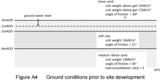
A4. Figure A4 shows the ground profile of a site to be developed as a retail park. The contractor proposesto preload the site using 2m of granular fill to consolidate the alluvial clay.
Determine the total and effective vertical and horizontal stress profiles:
(a) Before the ground is preloaded;
(b) Immediately after the 2m of granular fill is put in place. [8 marks]
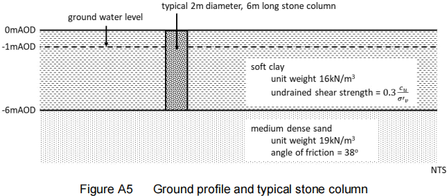
A5. Several 2m diameter 6m long stone columns are to be used to support an embankment. The columns will be 0.5m diameter and 7m deep as shown in Figure A5. Determine the maximum load a single stone column can carry. [8 marks]
Section B Each question is worth 20 marks. Attempt all questions
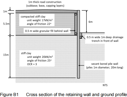
B1. Figure B1 shows the cross section of a retaining wall. The wall is a secant pile wall formed of 1m diameter 21.5m long reinforced concrete piles. The wall supports an approach embankment. A 1m thick road construction sits on compacted stiff clay such that the road surface is 6m above ground level. The base and subbase are formed of compacted sand and gravel. There is a 0.5m wide drainage blanket behind the wall and a 1m deep drainage trench in front of the wall. Check that the depth of embedment is adequate for a global factor of safety and comment on the factor of safety you obtain. [20 marks]
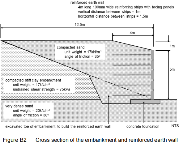
B2. Figure B2 shows a cross section through a reinforced earth wall used to steepen the sides of an embankment to allow the road the embankment carries to be widened. The toe of the embankment was excavated in sections to allow the wall to be built. Sand was used to construct the wall and raise the level of the embankment. 100mm wide, 4m long stainless steel strips were used to reinforce the wall with the surface protected with facing panels
(a) Determine the global factors of safety for the reinforced earth wall against overturning and sliding.
(b) Check that the length of the reinforcement strips is acceptable. Assume an appropriate factor of safety.
(c) Comment on the factors of safety [20 marks]
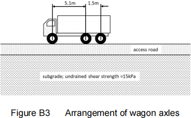
B3. An access road is to be built as part of the development of a port. Fill material is to be brought in by road using thee axle wagons which have a gross capacity of 33 tonnes. Allow for a 20% overload. The front axle has two wheels; the rear axles have four wheels each. The ten wheels are fitted with tyres operating at a pressure of 900kPa. Figure B3 shows the layout of the wheels. The subgrade is a firm clay has an undrained shear strength of 15kPa.
(a) Suggest an appropriate cross section for the access road which is supported by calculations to show it is adequate to prevent failure.
(b) Determine the optimum thickness of the access road construction assuming engineered fill costs £50/tonne placed and geogrid costs £3.50/sq m placed. The road will be 7mwide. [20 marks]