CAB302 Assignment 2: Vector Design Tool
Overview
Our company makes use of several pieces of hardware called plotters. These are devices for drawing vector-based graphics on various pieces of physical material from an input file, like a simplified version of PostScript. The challenge here is that our plotters make use of a proprietary design language called VEC which is not used by any other hardware or software on the market. This makes it difficult for our designers to create designs to be drawn on the plotters for two reasons:1. Our designers have to create new VEC files for the plotters by editing text files and entering in coordinates. This makes design a slow, laborious process, involving first sketching out th design on graph paper, then writing out the coordinates of each vertex, then typing out the file.
2. Because no software supports this proprietary format, our designers can only properly te their designs by using the plotting hardware. This is time-consuming as there are more designers than plotters and we need to be making better use of our resources.
The task we have for your team is to create a piece of Java software (from scratch) allowing for the preview of and editing of VEC files for the plotters. The idea is that this will allow designers to create their designs using a mouse in a WYSIWYG (what you see is what you get) environment instead of messing around with graph paper and editing text files. Furthermore, the software must also be able to load our existing VEC files, view them and edit their contents (e.g. to touch up or add to an existing design.)
The design for this program is left in your hands. You can look at programs intended for similar tasks to get an idea of how the UI should be structured, button placement etc. Please note that we care a great deal about the usability of this software as the software will be used by designers who are not necessarily computer experts. We want you to create for them a piece of software that is user friendly and intuitive, similar to tools like MS Paint.
The VEC file format
As explained before, the design files we send to the plotters are in a file format called VEC. This is a fairly simple file format. VEC files are just ASCII-format text files with UNIX-style line endings (that is, LF line endings). We do not mind if your application supports Windows-style (CR/LF) line endings or any other formats for its input files, but the files your application produces must be LF-format otherwise the plotters will not be able to read them properly.Each line of a VEC file describes a drawing operation. Here is a very basic VEC file, consisting of a single drawing command:
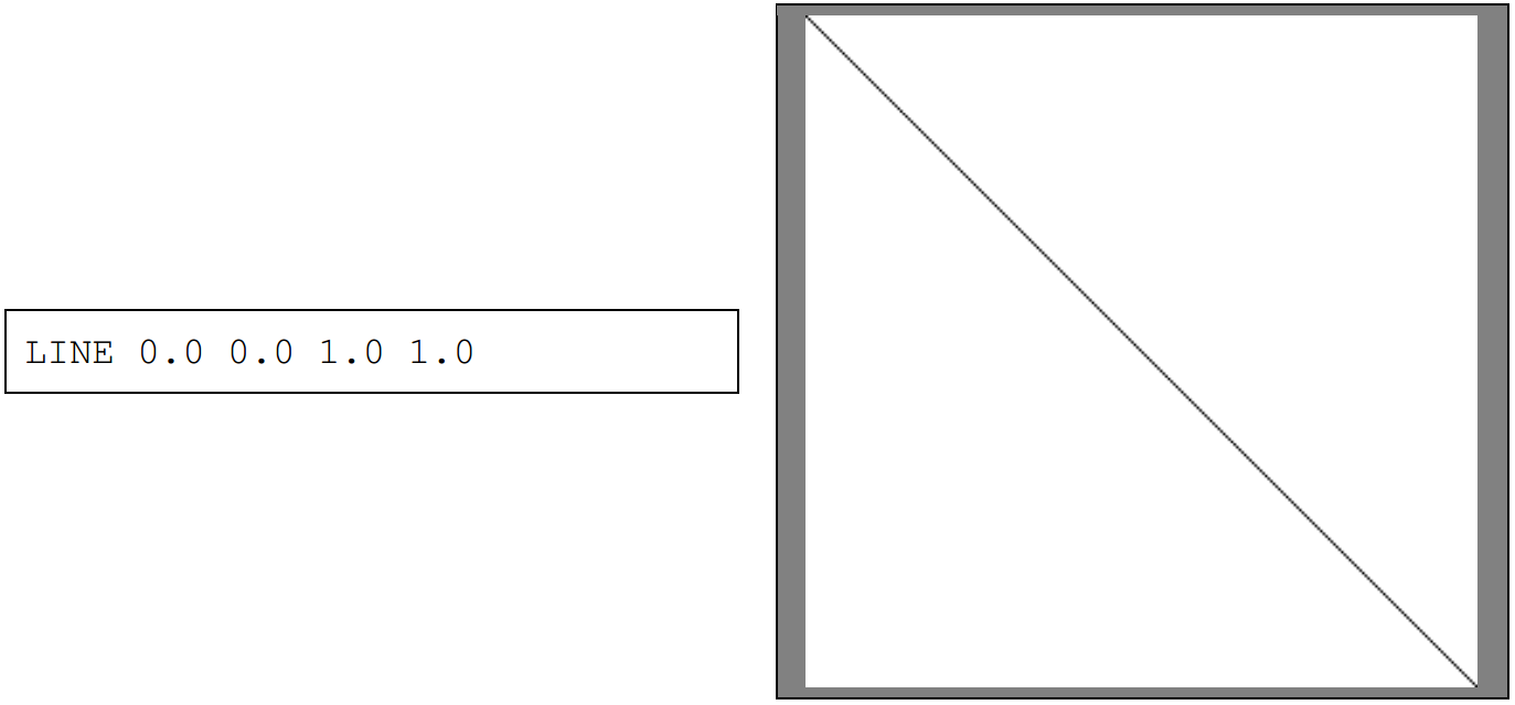
This is a drawing command called LINE. The syntax for LINE is LINE [x1] [y1] [x2] [y2]. The parameters in square brackets are the arguments for LINE. LINE draws a line from x1, y1 to x2, y2. In this case, x1=0.0, y1=0.0, x2=1.0 and y2=1.0, therefore LINE 0.0 0.0 1.0 1.0 draws a line from 0.0,0.0 to 1.0,1.0. The coordinates of 0.0,0.0 correspond to the top left of the image, while the coordinates of 1.0,1.0 correspond to the bottom right. Images are square and should be displayed with a 1:1 aspect ratio.
Naturally, more elaborate shapes can be achieved by sequencing multiple drawing commands, one per line. Here is an example of a six pointed star shape created with 12 LINE commands:
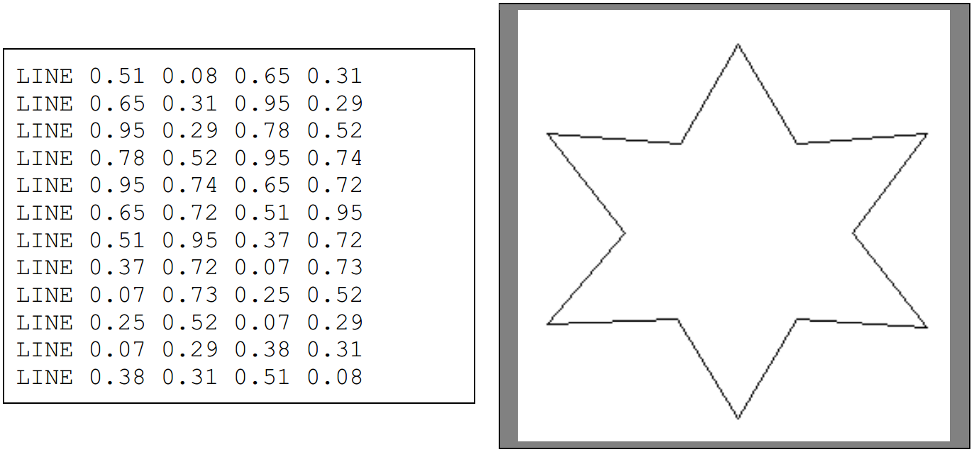
Each command is executed in the order in which it appears, which means that later commands can draw over earlier commands. The reason the coordinate system uses decimal values is related this this graphic format being a vector format – that is, rather than images being composed of discrete pixels, they are instead composed of simple drawing instructions like the LINE drawing instruction. This allows the images to appear crisp at any resolution. For example, the above star image might look like this at a resolution of 30x30:

And this at a resolution of 929x929:

This property is important as it means our designs can be scaled to a variety of sizes without changing the VEC file representing that image.
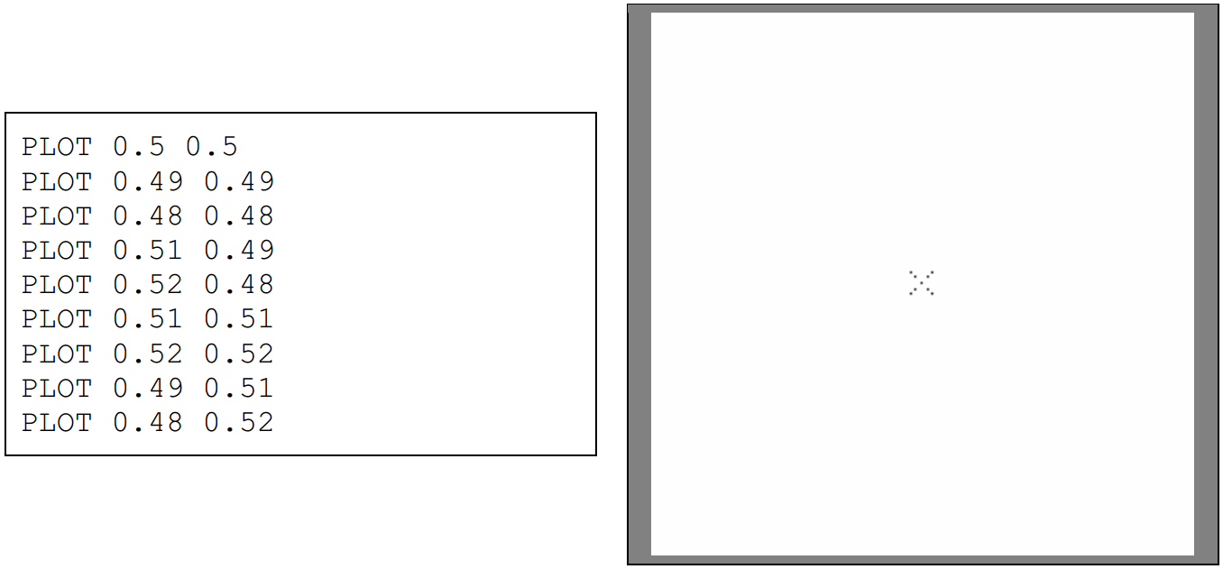
Two other drawing commands that are important are PLOT and RECTANGLE. PLOT [x] [y] simply draws a single dot at x,y, while RECTANGLE [x1] [y1] [x2] [y2] draws a rectangle with the top-left corner at x1,y1 and the bottom-right corner at x2,y2.
Example of PLOT:
Example of RECTANGLE.
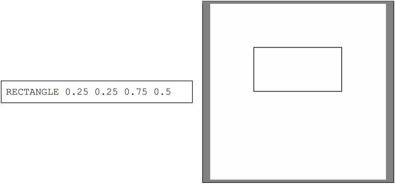
While it appears RECTANGLE simply substitutes for 4 LINE commands, the truth is that RECTANGLE has additional functionality beyond what LINE is capable of, as will be explained in the next section.
Colour drawing
Designs would get very boring without colour, and so the VEC language has commands that alter the colours used by subsequent drawing commands. The first is PEN [colour[, which accepts a HTMLformat 6-digit hexadecimal colour code and simply changes the primary colour used by the various drawing commands. For example:
PEN takes a colour in the form of #rrggbb, where each of rr, gg and bb is a 2 digit hexadecimal number describing a value from 0 to 255, which are used for the red, green and blue channels respectively. Example colours can be found at https://en.wikipedia.org/wiki/Web_colors. Note that case does not matter- PEN #fedcba describes the same colour as PEN #FEDCBA.
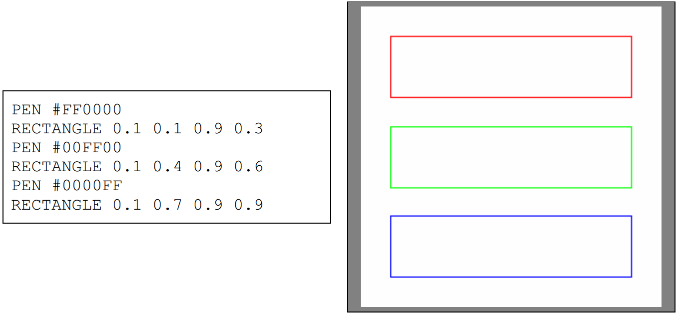
After a PEN command appears in the input file, henceforth all lines and dots drawn with various commands will be drawn with that colour (until that colour is changed by a subsequent PEN command). The default PEN colour is black, which means that all drawing instructions before the first PEN command will be drawn in that colour:
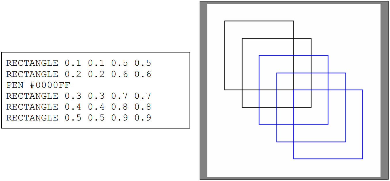
In this example, the first two squares drawn are drawn with the default pen colour (black), while the three that are drawn after the PEN command are drawn in #0000FF (blue).
The second colour command is called FILL. This assigns a colour to be used to fill rectangles and other shapes. This works in a similar way to PEN:
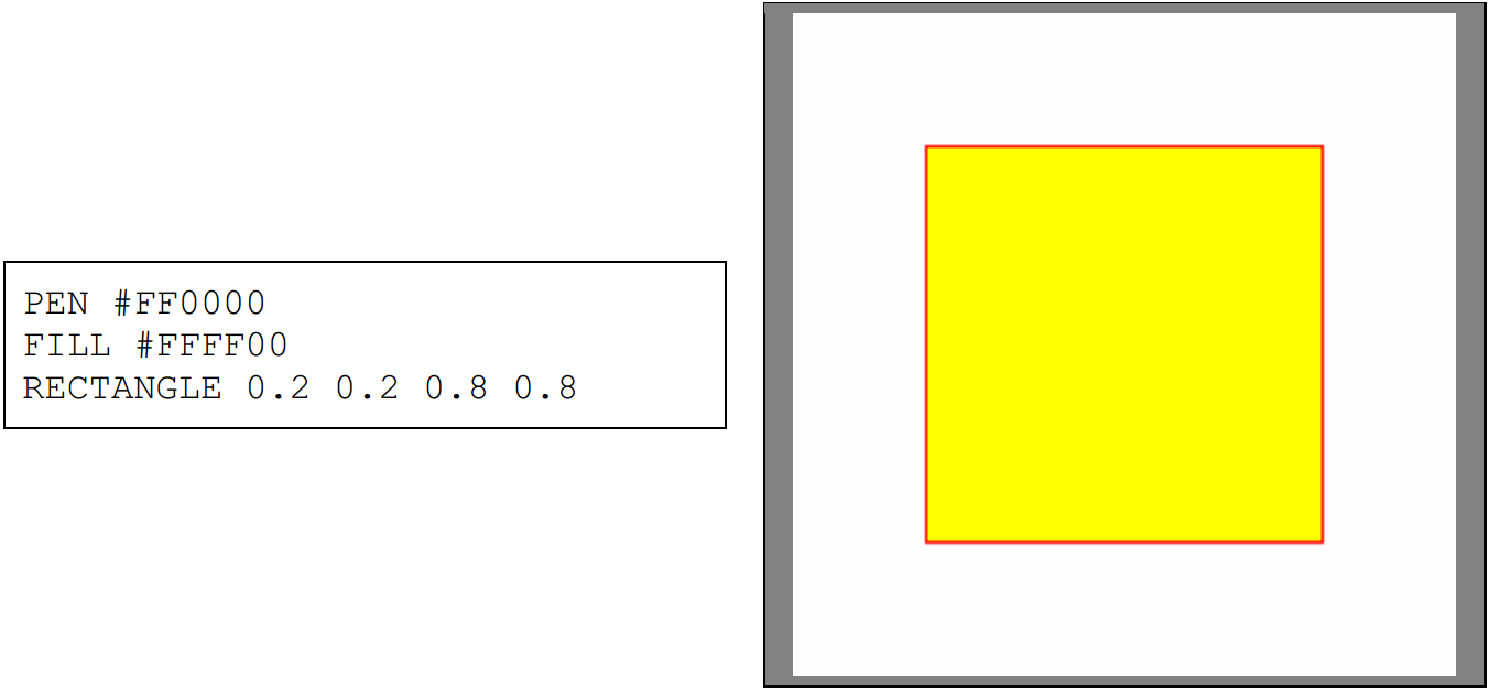
In this example PEN and FILL are used to set the outline and fill colour, which is used by the subsequent RECTANGLE. If more RECTANGLE commands were issued after that one, they would also use the same pen colour and fill colour.
Note that there is no default FILL colour; the default setting is to not fill in shapes at all. As an example of how this works in practice:
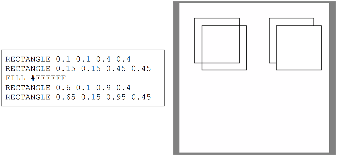
The two squares on the right have no fill colour, and therefore are drawn on top of each other without one erasing the other. The two squares on the right are drawn with a fill colour of white, and therefore the second one overlaps the first. In order to remove the fill colour entirely, the FILL OFF command can be used:
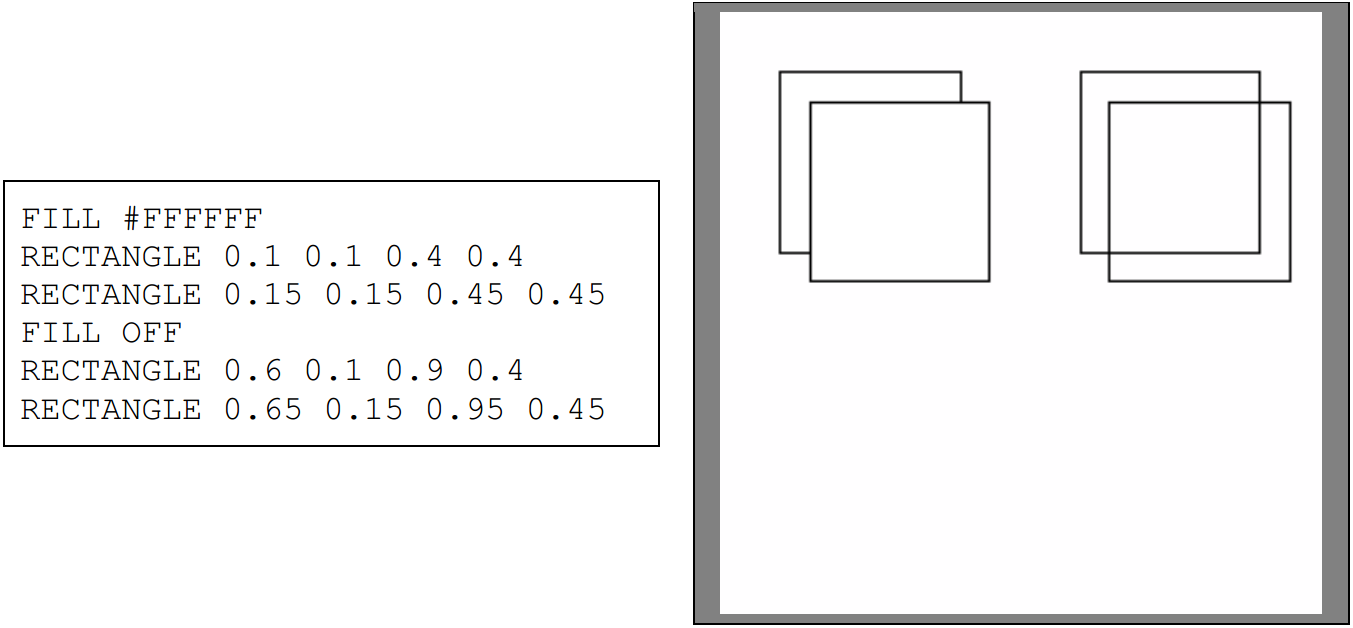
Note that there is no PEN OFF command; the lines are always drawn. Furthermore note that the FILL colour only applies to commands that draw shapes- PLOT and LINE do not use it, only PEN.
Other shapes
We have used RECTANGLE to demonstrate how colours apply to shapes, but the VEC language supports other shapes too, which are affected by PEN and FILL in the same way. Here are some of
them:
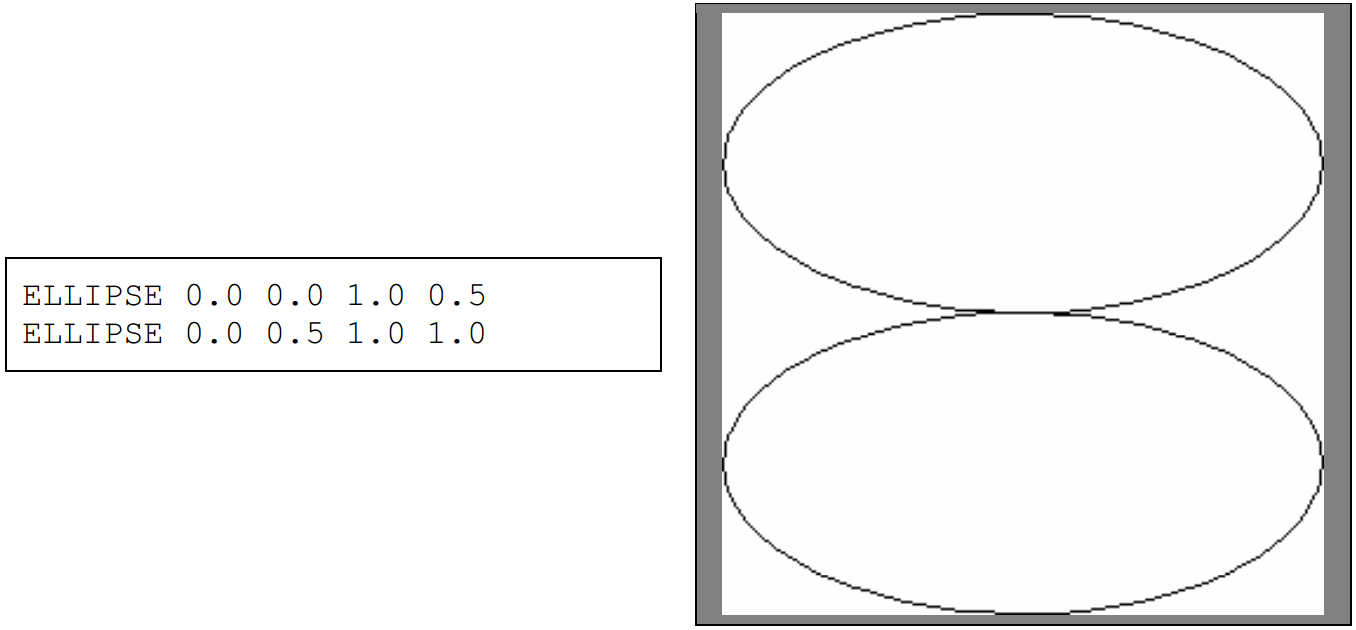
ELLIPSE [x1] [y1] [x2] [y2]
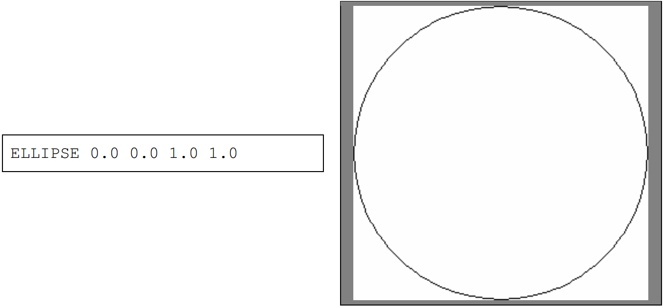
ELLIPSE draws an axis-aligned ellipse with extents that touch the bounds specified by the coordinates. These bounds also determine the shape of the ellipse – a circle if the bounds describe a square region, and an oval otherwise. Essentially, ELLIPSE will create the largest perfectly round circle/oval that can fit within the rectangle described by the x1,y1 and x2,y2 coordinates.
There is one last shape available in the VEC language- POLYGON. POLYGON is special because it can accept a variable number of arguments, and these arguments describe a polygon that is drawn by connecting the points with lines in the order in which they appear.
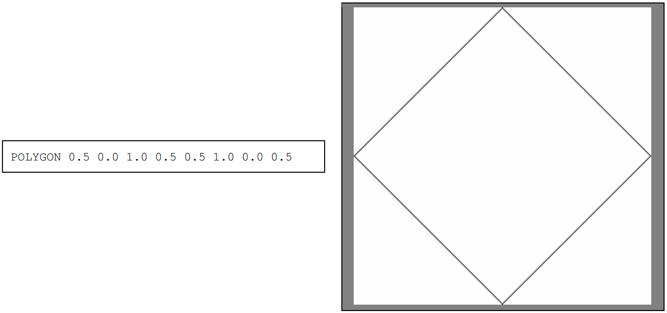
The syntax for the command is POLYGON [x1] [y1] [x2] [y2] [x3…] [y3…] and so on for any number of points. Lines are drawn between each two consecutive pairs of points- that is, x1,y1 to x2,y2, x2,y2 to x3,y3 and so forth, up to the very last point (xN,yN) which is in turn connected to x1,y1. These lines can overlap. As POLYGON describes a shape, it also works in conjunction with the FILL command.
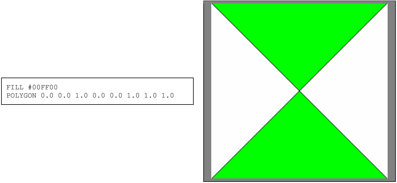
The POLYGON command allows elaborate shapes, like the star from earlier, to be drawn with a fill colour, as this is not achievable when images are composed of multiple LINE commands.
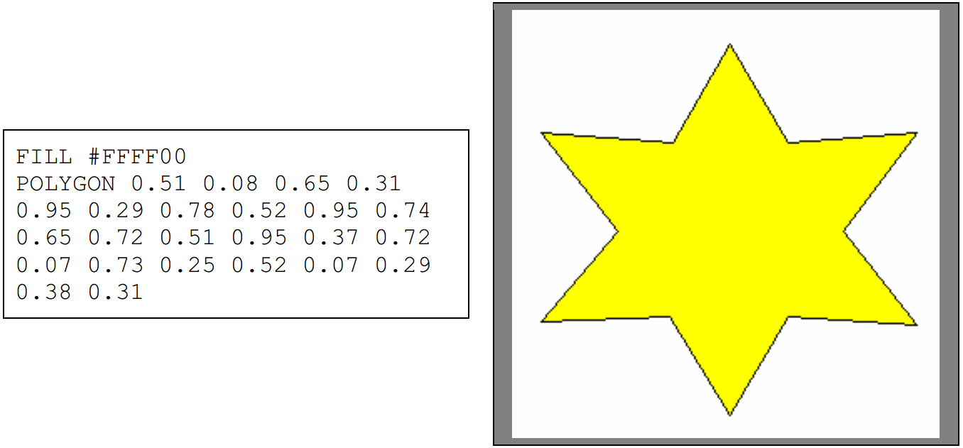
(Note that each command in the VEC language appears on a line by itself. This POLYGON command only appears to be multiple lines due to word wrapping.)
With this the basic VEC language commands have been described. While these commands only produce simple graphics individually, they can be combined together to produce elaborate designs.
Vector design tool
The task for this assignment is to create a Java program that can load and save VEC format images. The user interface design of the program is up to you, but use other graphics editing software as inspiration. Typically graphics editing software will have, at the very minimum, a menu bar with the typical ‘File’ menu containing items for opening and saving images, as well as a separate tool palette that is visible at all times, containing drawing tools, as well as a colour palette used to set colours to be used by those drawing tools.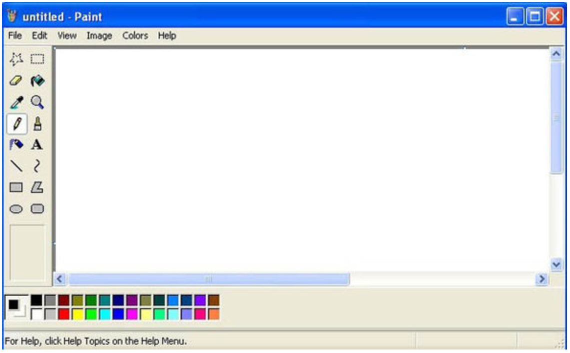
MS Paint from Windows XP, © Microsoft Corporation
For this assignment you will need to create a GUI application with similar controls. At the very least this will mean having a display canvas where your current design appears, buttons for loading and saving VEC files, drawing tools associated with each VEC drawing command (PLOT, LINE, RECTANGLE, ELLIPSE and POLYGON) and a colour palette allowing the user to set the colours used, which will generate appropriate PEN and FILL commands in the output file.
The load and save options must bring up file dialogs allowing the user to navigate the file system and find a location to load / save files. VEC format files will have the .VEC extension and the file selector should filter for that extension when opening files as well as use it by default when saving files.
The display canvas should be scaled based on the window size, such that the entire image can be seen and manipulated. I should be able to make this large so that I can work on fine details, and make it smaller so I can look at other stuff on the same screen at the same time. Unlike other paint programs, there is no concept of image size here- we work with vectors, so the top left of the canvas will correspond to 0.0,0.0 and the bottom right will correspond to 1.0,1.0 no matter what the size of the window is. As all VEC images are inherently square, the scaling should respect this and not show the images at incorrect aspect ratios.
The drawing tools should work as expected- you select a drawing tool, then you use the mouse on the image canvas to put the tool into practice. Again, pull up MS Paint or a similar drawing tool and try drawing some things, paying particular attention to exactly what happens when you select e.g. the line tool and try to draw a line with it- what happens when you press down the mouse button on the canvas, what happens when you release it and what is displayed to the user in the intermediate time. There are certain established user interface rules used by image editing tools and modelling these can be very helpful for creating predictable, intuitive user interfaces:
PLOT is simple enough – when the mouse is clicked, it should create a dot at that location
LINE, RECTANGLE and ELLIPSE should be implemented with the ‘press down mouse button’ Æ ‘drag mouse’ Æ ‘release mouse button’ model. That is, when you press the mouse button, it should start drawing the line, rectangle or ellipse at that position. When the mouse is moved to a new location and then the button is released, the new location should be used as the second pair of coordinates for that drawing operation. For example, if I select the rectangle tool and move the mouse to 0.2,0.2, press down on the mouse button,then drag the mouse to 0.8,0.8, it should draw a rectangle between those two pairs of coordinates. When I save the file it will contain something approximately like ‘RECTANGLE 0.2 0.2 0.8 0.8’. While I am dragging the mouse, the display should continually update, showing the shape that will be added to the image if I released the mouse at this location, similarly to how MS Paint and other similar programs work.
POLYGON is more complicated, and you may play around with different input models for this tool, as it needs to be able to place an arbitrary number of points. One solution is to have it place a point of the polygon with each mouse click, and having some other input end the sequence and close off the polygon (e.g. right click, spacebar, escape key.) Your user interface should provide enough information so that the user does not need to read help files to work out how to use your polygon drawing tool.
Your colour palette should have a set of colours available for quick selection, as well as the ability to bring up a colour picker that allows the user to select any possible colour. It must be possible to select the PEN and FILL colours separately.
Finally, there does need to be an Undo option (presented as a button or as a menu command, and additionally bound to the Ctrl+Z combination) that will erase the latest drawing operation performed. This should even work on images that have been freshly loaded from VEC files, erasing the last command in the file each time Undo is performed.
Additional functionality
The functionality described in the previous section is sufficient for a basic implementation. There are also several pieces of additional functionality we would like as well. If you are working by yourself, you don’t need to implement any of these. If your group consists of 2 people, implement at least one piece of additional functionality. If your group is of 3, implement at least two. If your group is of 4, implement at least three. Here are some suggested items of additional functionality:
1.Zoom. Let the user zoom in on the image and scroll around using a JScrollPane or similar component, in order for very fine details to be worked on. This can be handled with a magnifying glass control similar to Paint, or with a zoom % selection like in Word, or whatever else works.
2.Grid. By default the software should just let you place pixels and draw lines anywhere, but include a button that creates a grid that drawing operations will snap to. Make the grid size configurable (e.g. you might set a grid of 0.1,0.1, which would cause your drawing options to snap to the nearest multiple of 0.1). This will make the software more suited for drawing straight lines, laying out floorplans and the line). The grid should be displayed on the canvas while it is in operation, but should not be part of the saved image file. Multi-image support. When I open an image file / create a new image, rather than replacing my current image, it should load the new image in another separate window and allow me to work on them separately. This means your menu should have the option of closing individual images too.
3.Undo history support. Rather than purely having the Undo command for erasing drawing operations, there should be an additional button that brings up a list containing the history of drawing commands for that image, allowing me to step back and forth through the creation of that image (that is, I select a particular drawing command and I see what the image looks like with just the drawing commands leading up to that command.) This is a fairly advanced piece of functionality not available in editors like MS Paint, but you can google Photoshop’s ‘undo history’ and look at screenshots of it to get an idea of what we want from this feature.
4.BMP export. Most pieces of software that handle images can handle the BMP format, so being able to save images in this format is useful. However, the VEC format has no image dimension information and BMP images are a raster format, so the user should be asked o saving a BMP what its dimensions are. This should allow us to do things like save VEC images as very large (e.g. 4096x4096) BMP images to preserve as much detail as possible, making the software more generally useful.
These are the main ones. You can come up with your own pieces of additional functionality to include in place of these, but that functionality will be compared against these suggested items to determine if what you have implemented is of similar complexity and usefulness. Multiple smaller pieces of functionality can substitute for one large piece of additional functionality, if you so prefer.
Software architecture
Similarly to the user interface, the architecture of your project (what your classes are and how they interact with other classes) is left up to your team- however, as this is an advanced object-oriented programming unit you will be graded on the architecture you come up with to support this project.
You will need to document your class hierarchy and the interactions between classes in the report you submit alongside the project, and as this is an advanced OOP unit you are also expected to make use of advanced object oriented programming principles – namely, abstraction, encapsulation, inheritance and polymorphism. Some of these will come more naturally than others, but you are expected to feature some examples of each and describe these in your report. The architecture you create should be developed with an eye for extensibility; you will be graded on how easily your software can be improved with new features. Obvious areas where extensibility hould be a focus include:
• The commands available in the VEC language – adding new ones to support features added to newer plotting machines should be straightforward and not rely on changing the code in too many places.
• The graphical tools available – if the client later decides they want a spray-can tool or flood fill tool, the difficulty required to add these should not be much more than just implementing their code.
Source control and teamwork
Whether you are attempting this assignment as an individual or as a team, you are required to use Git to track development of your assignment. This also doesn’t mean making occasional commits with large amounts of code added each time – you should make commits early and frequently. If in doubt, it’s best to be on the side of having too many commits rather than too few. Note that you do not need a detailed commit message with every single commit.
If you are working in a team, you should set up a private Git repository on a site like Bitbucket and use it as the central repository. There are two main ways you can handle having your team members contribute to the project:
• Give each person in your team access to the repository. Bitbucket can be configured to do this from ‘User and group access’. This way anyone can commit changes to the repository.
• Everyone clones the repository into their own Bitbucket accounts and contributes code through branch management and pull requests. See https://www.atlassian.com/git/tutorials/making-a-pull-request for more detail. If this confuses you, just giving the team commit access to the repository may be easier.
Either of these approaches is acceptable. What is important is that every team member sets up their Git username and email address correctly so that it is clear exactly what every member contributed. Do not commit code under someone else’s name. If there are problems with getting the shared repository working, in the very worst case you can make commits under your own name locally and send the entire directory around / share it via Dropbox / anything else. We will assume that someone’s contributions are everything that person committed.
When you submit the assignment via Blackboard, make sure you submit the entire project directory including the hidden .git directory. Note that IntelliJ’s ‘Export to Zip File’ option will not include this directory. On Windows, the ‘Send to Æ Compressed (zipped) folder’ functionality in Explorer will work nicely. Just make sure you choose the directory that contains your project, not just all the files in the directory, because if you don’t have ‘Show hidden items’ on it will not select those.
Agile software development
You are expected to make use of Agile software development principles in the development of this project from the beginning. This can mean test-driven development, but does not necessarily need to be. Ultimately one of the most important parts of Agile is in ensuring that you always have a working copy of the latest version of the software- things don’t just come together at the last minute; instead, the software evolves towards having greater capability, stability and quality. In your report you will be required to document how you have made use of Agile principles, and your efforts in this area will be graded based on how the commit history of your Git repository supports this.
In addition, this is not an easy software development task. You are working from scratch, on a major project, with a tight time limit and a team that you may not have worked with before. These are all individually factors with a high level of risk and the combination of them increases the amount of risk geometrically. As a result, you should be attempting to ameliorate risk wherever you can, and the best way of doing this is to make sure you always have a working version of your software. You will be marked only on the features you implement that are actually working in the software you submit, so if you submit a broken version of your software, your marks will likely be considerably worse than if you submit an earlier version of the software that had less functionality but at least ran properly. Begin your commitment to always having a working version of the software from the beginning, even if all you have at the start is a basic form that doesn’t do anything. Commit this into the repository and then continue working from there.
Agile development is not just required as part of the assignment specification; it’s also a good idea.
Unit testing
Whether you make use of test-driven development or not, you are expected to maintain a suite of unit tests that thoroughly test all parts of your project that can be reasonably unit tested (that is, anything that is not GUI code, file access code etc.) These unit tests will be evaluated for their usefulness and test coverage.Source code documentation
You are required to document your source code with both regular comments (// and /* */ comments in the bodies of your methods describing the intention of the code they precede) and JavaDoc-style comments (/**-style block comments preceding classes and methods, thoroughly documenting the semantics of the class/method, the arguments they take, any return values and any exceptions thrown). Furthermore, you are required to generate JavaDoc HTML documentationfrom these comments and submit it with your assignment.
Development environment and external libraries
Your software must be created with the Java JDK 11. The choice of IDE is up to you, but as your project will be marked with IntelliJ it is recommended that you at least port your project into IntelliJ before submitting it.
You can use AWT, Swing or JavaFX to create the GUI used in this assignment. Swing is recommended. The only libraries you can use that are external to the JDK 11 are JavaFX and JUnit 5.
You are allowed to make use of tools like IntelliJ’s GUI Designer to create your GUI, as long as external libraries are not used.
What you are required to submit
• Your software project, in .zip form, containing:Your project source code.
The hidden .git directory that holds the entire commit history of your project, which we will be using to verify appropriate software development lifecycle processes were followed. As noted before, the IntelliJ ‘Export to Zip File’ menu option does not include the .git directory, so use another tool (like Send To Æ Compressed (zipped) folder) and make sure the created .zip file contains that directory. Turn on ‘show hidden files’ if necessary.
The JavaDoc-generated documentation for your project.
The unit tests for your project. Your marker will take your .zip file, extract it into a directory, then open it in IntelliJ and expect it to basically run as-is. The marker will go to limited effort to get your software working if it does not run out of the box, so it is in your best interests to make sure that things work as-is.
A report (in .docx or .pdf format), containing at minimum the following:
A statement of completeness, describing what functionality your team managed to implement – both the basic functionality and any applicable additional functionality (note that you must implement 1 item of additional functionality for each person in your team beyond the first.)
A statement describing how your team made use of Agile software development processes. If you used test-driven development, describe this here. Otherwise, describe other relevant processes (e.g. iterative design-code-test stages).
Documentation of your software architecture, describing all the classes that make up your project and how they interact with the other classes to bring your project together.
Abstraction
Encapsulation
Inheritance
Polymorphism
Documentation of how to use your software, with associated screenshots showcasing all the items of functionality.
2019-05-07