CA19 Fault analysis
Hello, dear friend, you can consult us at any time if you have any questions, add WeChat: daixieit
Experiment No : CA19
Title : Fault analysis
Objective : 1. To study the fault levels and flows ofa simple system (without load).
2. To study the fault levels of a 2-area system under different loading conditions using PowerWorld Simulator.
Part A
Procedures
a) Develop a 5-bus 2-generator 132kV system shown in Fig. A with the following settings:
i. Power base, SB = 100 MVA
ii. Voltage base, VB = 132 kV
iii. Nominal Voltage = 132 kV, i.e. 1 pu
Refer to Annex 1 for guidance on building a multi-bus system in PowerWorld.
b) Examine the fault levels at various buses.
c) With a fault occurred on bus F, examine the fault flows in all the circuits and the infeeds from the two generators.
d) Verify the results from (b) and (c) using hand calculations.
e) Determine how an outage of generator GB or circuit BC would affect the results in (b).
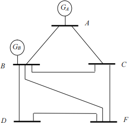
Fig. A 5-bus system
|
Table A1: System impedance |
|
|
(pu. on 100MVA base) |
|
|
|
|
|
Generator (pu) |
|
|
GA |
0.1 |
|
GB |
0.2 |
|
Circuit (pu) |
|
|
AB |
0.1 |
|
AC |
0.2 |
|
BC |
0.125 |
|
BD |
0.25 |
|
BF |
0.333 |
|
CF |
0.5 |
|
DF |
0.167 |
Part B
Fig. B shows a 132kV interconnected system, with system data shown in Annex 2.
Procedures
a) Using the sample system provided, establish the base case in Annex 2, with nominal loads as given in Table B1, generator groups as given in Table B2, and the following settings:
i. Power base, SB = 100 MVA
ii. Voltage base, VB = 132 kV
iii. Nominal Voltage = 132 kV, i.e. 1 pu
iv. Bus 1 as ‘slack’ and bus 2 to 7 as ‘PV’, with voltages set at 138 kV, i.e. 1.045 pu
b) Run a load flow on the base case, then perform a fault analysis to obtain fault levels for comparison with cases in (c) and (d).
c) Based on the base case in (a), modify the system as follows:
Case 1: Increase the MW/MVAr load of each bus by 20%
Case 2: Increase the number of generator sets in A1 to 4
Case 3: Add a parallel line to m1
Case 4: Add a parallel line to m2
where m1 & m2 are heavily loaded tie-lines, and there is no need to change the MW output of any generator group.
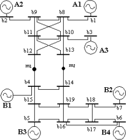
Fig. B: 19-bus, 7-generator, 2-area interconnected system
Discussion:
Create a table of fault level results under different scenarios.
Compare and comment on how fault levels are affected by system operating conditions.
2026-03-13
Power Transmission and Distribution