CEGE0024 STRUCTURES AND MATERIALS
Hello, dear friend, you can consult us at any time if you have any questions, add WeChat: daixieit
CEGE0024 STRUCTURES AND MATERIALS
STRUCTURES COURSEWORK HANDOUT: PLASTIC DESIGN AND MODELLING
This group coursework consists of two parts, reflecting the two main areas covered in the module:
1. Plastic analysis
2. Finite Element (FE) modelling
Together, the coursework contributes 20% of the total module mark.
• Part 1 – Plastic Analysis contributes 2.5% of the overall module mark
• Part 2 – Finite Element Modelling contributes 17.5% of the overall module mark
Both parts must be completed and submitted as a single coursework submission.
Group mark moderation mechanisms will be used. Details will be confirmed later.
Requirements for submission
• Submission via Moodle by 27/03/26, 17:00 (UK time)
• Three submission files only: GroupXX.pdf, groupXX_global.gwb and groupXX_construction.gwb
• This assessment is not eligible for Reasonable Academic Adjustment (RAA) or Delayed Assessment Pass (DAP) as it is designed to be inclusive.
• Submissions must:
i. Be legible (incl. Adequate font size)
ii. Include relevant supporting calculation/references,
iii. Not exceed the page limit set for each deliverable.
iv. Comply with file names/formats
v. Use the newest version of GSA software.
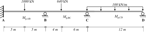
Part 1: Plastic design of a continuous beam
The continuous beam shown in Figure 1 is to be designed using plastic methods.
Assume that the beam has full lateral restraint.
Design requirements
You are required to design the beam such that the solution is economical and practical to construct. Standard steel universal beam (UB) sections may be used with any strengthening methods using mild steel.
Deliverables
1. Hand calculations (2 x A4 pages maximum).
Provide clear hand calculations showing:
• Collapse mechanism
• The required plastic moment of resistance for each span (Mp,AB, Mp,BC, Mp,CD).
• Key assumptions
Calculations should be neat, logical and easy to follow.
2. Line sketch and justification (1 x A4 page maximum).
Provide a clear line sketch of the continuous beam showing selected members size for each span; and/or location of any strength measures. Accompany the sketch with a concise justification explaining:
• Why the chosen solution is economical
• Why it is practical to construct
Assessment Criteria
Marks will be awarded based on:
• Correct identification of collapse mechanisms
• Logical and accurate plastic analysis
• Clarity of sketches and explanations
• Practicality and constructability of the proposed design
Part 2: Finite element modelling
The Heathrow Terminal 5 roof structure will be used as a case study to develop a simplified planar (2D) global Finite Element (FE) model of the structural system.
Provided Information
Supplementary documentation provides the following:
• General geometry and dimensions of the roof structure (excluding wall thickness of the arch rafter, tusk rafter, and strap)
• Dead and live load values
• General project and construction information
Any additional parameters required for modelling but not explicitly provided must be clearly stated, justified, and documented within the deliverables.
Modelling Assumptions and Simplifications
For the purposes of this assignment, the following simplifications shall be applied:
• Assume elastic modulus of all members is 200GPa.
• Only vertical, symmetric loading is to be considered with the magnitudes specified in the supplementary documents.
• Each structural member shall be assumed to have a uniform wall thickness along its length. Assume the arch rafter and tusk rafter have a wall thickness of 50mm. Assume the individual strap plates have a width of 500mm, thickness of 40mm and positioned 560mm centres apart.
• Prestressing of the high tie is assumed to be applied after the complete erection of the structure, unless otherwise stated for sensitivity comparison. Assume 450MPa prestress is applied to the high tie.
These simplifications are intended to focus attention on modelling strategy and interpretation.
Objectives
• Qualitatively define and explain the global behaviour of a structural system
• Apply the basic principles of a FE modelling process
• Develop and justify a validated global FE model
• Assess the sensitivity of FE results to modelling assumptions
• Extract boundary conditions suitable for use in a more detailed local analysis
• Communicate modelling decisions and uncertainty clearly and professionally
Deliverables
1. Structural Idealisation Sketch (1 x A3 or A4 page maximum)
Provide a clear sketch of the planar (2D) FE model idealisation of the roof structure showing:
• Overall geometry and key dimensions
• Exact position of nodes and beam elements
• Support conditions and any releases
This sketch should clearly communicate how the real structure has been idealised into an FE model.
2. Material, Section, and Loading Data (1 x A4 page maximum)
Provide a summary of:
• Material properties
• Section properties
• The critical vertical load combination based on the provided project information
All assumptions must be clearly identified and justified.
3. Initial Model Validation (1 x A4 page maximum)
Provide an initial validation of the FE model using simple hand calculations.
You must clearly state:
• The assumptions made
• What aspects of the model are validated
• The conclusions drawn regarding model adequacy
4. Mesh Refinement Sensitivity Study (1 x A4 page maximum)
Provide a summary of a sensitivity study that investigate the influence of mesh refinement on the FE results. You should:
• Analyse at least three levels of mesh refinement
• Compare key response quantities (e.g. internal forces, displacements)
• Define the mesh density that is sufficient for the modelling purpose
5. Influence of Prestressing Assumptions (1 x A4 page maximum)
Qualitatively and quantitatively assess the influence of assuming that prestressing of the high tie occurs after full erection, compared with the construction process described in the supplementary documentation.
You should:
• Compare the structural response under the two assumptions
• Comment on differences in internal forces and overall behaviour
• Discuss the implications for design and construction tolerances
Full construction stage modelling is not required. Comparative reasoning based on simplified models is sufficient.
6. Boundary Conditions for more detailed analysis (1 x A4 page maximum)
Assuming the rafter splice connection between the tusk rafter and arch rafter is a candidate for more detailed analysis, provide:
• A clear sketch showing the boundary conditions you would apply to a local FE model of this connection
• A description of the forces and/or displacements that would be imposed
You are not required to build the detailed FE model. The focus is on appropriate boundary condition definition.
7. Electronic Model Files
Submit two electronic FE model files:
a. The global FE model of the entire roof structure
b. A modified model used to investigate the prestressing assumption described in Deliverable 5.
Models must be clearly named and organised.
Assessment Criteria
Marks will be awarded based on:
• Quality and clarity of modelling assumptions
• Understanding of global structural behaviour
• Quality of sensitivity analysis and interpretation
• Appropriateness of validation checks
• Clarity and professionalism of presentation
Marks will not be awarded for:
• Excessive model complexity
• Over-refined meshes without justification
• Uninterpreted software output
2026-03-04
PLASTIC DESIGN AND MODELLING