ELEC3575: Electric Power Systems Laboratory (Software Lab) Part B
Hello, dear friend, you can consult us at any time if you have any questions, add WeChat: daixieit
ELEC3575: Electric Power Systems Laboratory (Software Lab)
Part B: Distribution Network Reinforcement, Expansion and (N-1) Security Analysis in PowerFactory
1 Review
Please review the following items in your lecture notes before the lab:
- (N-1) criterion;
- Load flow calculation;
- Reactive power compensation.
2 Introduction
2.1 Problem Statement and Tasks
In this lab, we will analyse and expand the 110 kV electric distribution network shown in Fig. 1 using the software PowerFactory. The network is composed of 4 substations A, B, C, and D (referred to as buses). Buses B and C are each connected to bus A via an overhead line (OL), while bus D is connected to bus A via a cable. The line characteristics are indicated in Table 1. At each bus a load (A1, B1, C1, D1) is placed, representing the aggregated power demand of the customers at that node. The load demand is given in Table 2. The distribution network is supplied from a high voltage (220 kV) transmission system via a 220/110 kV transformer (power rating of 250 MVA) that is connected to bus A.
A new area composed of an industrial (load C2) and a residential (load C3) load is supposed to be built at bus C. To accommodate the increase in load demand, a new power station is planned to be constructed at bus E. Bus E is a well-suited location for the new power station, as it is close to a river (for cooling water) and the railway line (for fuel transport). To connect the new power station to the existing infrastructure, the distribution network has to be expanded. Your main task is to plan, implement, and successfully test this expansion. To do this, you may use 110 kV overhead lines of the same type as those connecting buses A, B, and C. In addition, your solution needs to satisfy the (N-1) criterion for buses B and C.
To accomplish the above objectives, you need to solve the following tasks.
Task 1) Analysis and possible reinforcement of existing distribution network;
Task 2) Distribution network expansion: line planning, dimensioning, implementation, and analysis guaranteeing (N-1) security at buses B and C.
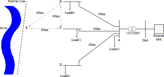
Figure 1: Considered 110 kV distribution network
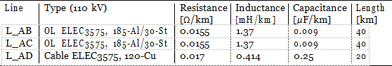
Table 1: Line Characteristics
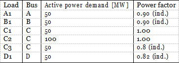
Table 2: Load demand
2.2 Learning Objectives
After successful completion of this lab, you should …
• …be able to perform load flow calculations and load flow analysis in PowerFactory;
• …conduct a network expansion design ensuring (N-1) security of specific network buses;
• …implement new equipment in PowerFactory and verify its functioning according to your design specifications.
3 Getting Started
To get started, do the following.
1. Download the “ELEC3575_PowerSystemsLab.pfd” file from the VLE and save it on your local PC.
2. Find “PowerFactory” on the AppsAnywhere website and start it.
3. Close all windows that may pop up until you can see the main PowerFactory workspace.
4. Click on the menu item “File” (upper-left corner) and select “Import → Data”. Navigate to the folder, where you saved the *.pfd file and select that.
5. Click on the “data manager” in the main toolbar (the first item from the left ![]() ), then the data manager window will pop up.
), then the data manager window will pop up.
6. Click the arrow “>” beside your user name to see all subsections below your username.
7. Right-click on “ELEC3575- Power Systems Lab”, and then select “Active”.
8. Now you should see a network in the main PowerFactory workspace. The network represents the 110 kV distribution system shown in Fig. 1. As in the previous lab, we model buses using the “Single Busbar System” element of PowerFactory (the standard PowerFactory components are shown on the right-hand side of your main workspace window).
9. Check that the lines “L_AB” and “L_AC” are of the type “Overhead line ELEC3575” and that the line “L_AD” is of the type “Cable ELEC3575”.
10. Check the load demand and power factor at buses A, B, C, and D. What is particular about the load demand C1 at bus C? Can you explain how such a situation could arise in a real-world situation?
4 Task 1: Analysis and Reinforcement of Existing Network
In this task, you will evaluate the performance of the existing distribution network.
Task 1.1 Run a load flow simulation. To do this, click on the tab “Calculate Load Flow” (shown by ![]() ) in the main toolbar. The Load Flow Calculation window pops up. Make sure the “Calculation Method” is set to “AC Load Flow, balanced, positive sequence” and leave all other settings unchanged. Click on “Execute”.
) in the main toolbar. The Load Flow Calculation window pops up. Make sure the “Calculation Method” is set to “AC Load Flow, balanced, positive sequence” and leave all other settings unchanged. Click on “Execute”.
Task 1.2 Evaluate the load flow results.
Task 1.3 Are the voltage magnitudes at all buses within satisfactory limits (i.e., ±5% of the nominal grid voltage)? Are the line loadings within their limits?
Task 1.4 Now use the “Heatmap” function of PowerFactory to illustrate the current network status. Select “View → Heatmap”. A window should pop up. Click on the → next to the “Settings” field. Again, a new window pops up. Make sure to only tick “3. Other” and untick options 1 and 2. In addition, set the options in “3. Other” to “Results” and “Voltages / Loading”. Then click “OK” and “Execute”. Does the displayed coloring coincide with your previous observations? Justify your answer.
Note: Colour maps in the form of heat maps and alike are a popular tool in network planning and operation to visualise the network status. They are also particularly suited to explain your power system analysis results to potential non-power-engineering colleagues working, e.g. in managing, market- or policy-oriented positions.
Task 1.5 If you detect any problems, add suitable equipment to improve the network operation. In particular, add a shunt capacitor at Bus D. How does this capacitor need to be dimensioned? Also, make sure to assign an appropriate nominal voltage to the capacitor element.
Hint:
QLoad = PLoad tan(φ), QC,1ϕ = −ωC|V |2.
Task 1.6 Re-run the load flow calculation. Has the network status improved? Justify your answer by inspecting the load flow results. Verify your observations by using again the “Heatmap” function. If the line loading is still above 93%, your capacitive compensator needs to be adjusted. Why is it in the current situation not optimal to set the compensation identical to the reactive power demand of the load?
Hint: The capacitive “charging” power of a cable of length ℓ is
QCable,1ϕ = −ωC′ℓ|V |2
and approximately half of it is “compensated” by the inductive load at bus D. Task 1.7 Is the network operating status now acceptable? How could it be further improved?
Only provide suggestions, an actual implementation is not required.
5 Task 2: Network Expansion and (N-1) Security Analysis
Now, you will expand the network infrastructure to incorporate the new loads C2 and C3 at bus C as well as the new power station at bus E. Your proposed expansion must also satisfy the (N-1) criterion for buses B and C. This task is split into three subtasks:
Task 2.1 Expansion planning;
Task 2.2 Implementation of the new power station and loads in PowerFactory; Task 2.3 (N-1) security analysis.
5.1 Task 2.1: Expansion Planning
For the network expansion planning, follow the steps indicated below.
Task 2.1.1 Explain why a new power station is needed to accommodate the new load demand at bus C.
Task 2.1.2 Calculate the apparent power demand at bus B.
Task 2.1.3 Calculate the apparent power demand of bus C including the new loads.
Task 2.1.4 Calculate the thermal power limit for the “OL ELEC3575”. Assume the maximal long-term admissible current density for one conductor is J = 3.5 A/mm2.
Hints:
• Thermal current limit (per conductor, i.e. per phase):
ITh,max = J · A
where A is the cross-section of the conductor strand (see Table 1 and Lecture Part 5)
• Thermal power limit:
STh,max = 3VLNITh,max
Task 2.1.5 Using your results from the previous task, calculate the required number of OLs to ensure (N-1) security of the loads at buses C and B. Follow these steps and use the hints indicated below.
a) Calculate the number of required three-phase OLs of the line type OL ELEC3575 needed to supply the load at bus B without violating the thermal power limits of the lines.
b) Based on your result, calculate the number of required three-phase OLs of the line type OL ELEC3575 needed to supply the load at bus B with (N-1) security.
c) Perform the same calculations for the loads at bus C.
d) Given the existing topology of the distribution network, suggest two different options (i.e. network topologies) that would allow to satisfy the (N-1) security for buses B and C, while also incorporating bus E into the network. Sketch your proposed solutions and discuss them with one of the lab demonstrators.
Hints:
• Number of required three-phase power lines to transmit given apparent power SL at nominal voltage without violating thermal line limits:

• Number of required three-phase power lines to transmit given apparent power SL at nominal voltage without violating thermal line limits and ensuring (N-1) criterion:
n(N-1) = nTh + 1
5.2 Task 2.2: Implementation of the new Power Station and Loads in Power Factory
Task 2.2.1 Add the new loads C2 and C3 to bus C in your PowerFactory model. Use the “General Load” element shown by ![]() in the PowerFactory library. Name the loads “LoadC2” and “LoadC3”. Adjust the load demand settings in the “Load Flow” tab of each new load according to the values in Table 2.
in the PowerFactory library. Name the loads “LoadC2” and “LoadC3”. Adjust the load demand settings in the “Load Flow” tab of each new load according to the values in Table 2.
Task 2.2.2 Add the new bus E to your PowerFactory model. Use the “Single Busbar System” element shown by ![]() from the PowerFactory library. Rename the new station to “Bus E” and make sure that the Type is set to “Bar-110 kV”. To do this, click on “˅” in front of Type and then select “Select type”. A new window pops up. Above your username, expand DIgSILENT Library by clicking “˃” beside it (after clicking, “˃” is changed to “˅”). Then select “Equipment type”, “Busbars”, and “v001”. Now, four different busbars appear in the window beside the menu window. Select Bar-110 kV and click “OK”.
from the PowerFactory library. Rename the new station to “Bus E” and make sure that the Type is set to “Bar-110 kV”. To do this, click on “˅” in front of Type and then select “Select type”. A new window pops up. Above your username, expand DIgSILENT Library by clicking “˃” beside it (after clicking, “˃” is changed to “˅”). Then select “Equipment type”, “Busbars”, and “v001”. Now, four different busbars appear in the window beside the menu window. Select Bar-110 kV and click “OK”.
Task 2.2.3 Add the new power station to bus E. The new power station operates at 16 kV and is connected to bus E via a 16/110 kV step-up transformer.
a) Add another new bus to the network (again, using the “Single Busbar System” element), and call that bus “Bus SG”. There is no Global Type for a 16 kV busbar defined in PowerFactory, but there is already a custom-defined one for the lab. Click “˅” beside Type, and “select type”. A new window pops up. Click on “˃” beside your username, select “ELEC3575- Power Systems Lab”, “Library” and “Equipment Type Library”. Now, “Bar-16 kV” appears in the window in front of the menu window. Select it and click on “OK”. Do not forget to change the Line-Line voltage in the Nominal voltage section to 16 kV. Then, click on “OK”.
b) Now, we add the synchronous machine representing the new power station to the model. Do this by selecting the item “Synchronous Machine” shown by ![]() from the PowerFactory library and connecting it to one of the terminals of bus SG. Now you need to define the machine type. Do this by clicking on “˅” beside Type and “Select Type”. A new window pops up. Select “Synchronous Machine ELEC3575” and click “OK”. What is the nominal apparent power of this machine? (You can find this value by clicking on the arrow “→” in front of “Type”).
from the PowerFactory library and connecting it to one of the terminals of bus SG. Now you need to define the machine type. Do this by clicking on “˅” beside Type and “Select Type”. A new window pops up. Select “Synchronous Machine ELEC3575” and click “OK”. What is the nominal apparent power of this machine? (You can find this value by clicking on the arrow “→” in front of “Type”).
c) Next, bus SG has to be connected to bus E via a 2-winding transformer. Add the transformer shown by ![]() in the PowerFactory library to your model and connect it to the respective buses. To select the type, click on “˅” beside Type and “Select Type”. Then, choose 16\110 kV Transformer ELEC3575. Make sure the HV and LV sides are set correctly and flip them otherwise.
in the PowerFactory library to your model and connect it to the respective buses. To select the type, click on “˅” beside Type and “Select Type”. Then, choose 16\110 kV Transformer ELEC3575. Make sure the HV and LV sides are set correctly and flip them otherwise.
d) Now, you need to set the right operating set points and options for the synchronous machine at bus SG. Open the machine parameter window and select the tab “Load Flow”. On the upper right-hand side, there is a drop-down menu called “Local Controller”. Study the different options. What do they imply for the operation of the machine? Select “Const. V” as option.
e) In the “Dispatch” properties, leave the “Input Mode” on “Default”. In the field “Active Power” you can specify how much active power the machine should generate. Based on the new load demand at bus C, how would you choose the active power setpoint?
f) Make sure the “Voltage” is set to 1.0 pu. What value would you enter in the field “Reactive Power”? Does it play any role at all if the “Local Controller” is set to “Const. V”?
5.3 Task 2.3: Network Expansion and (N-1) Security Analysis in Power Factory
In this part of the lab, you will implement both your solutions for the network expansion proposed in Task 2.1 in PowerFactory and analyse which solution is more beneficial for the (N-1) secure operation of the system.
Task 2.3.1 Implement the first of your proposed (N-1) secure network topologies.
a) Run a load flow calculation to test your implementation. Fix any errors that may occur. How would you judge the resulting network operating state?
b) If necessary, can you think of an easy way to improve the voltage behavior at buses B and C without the need to install any further reactive power compensation equipment? Test your proposed solution.
Hint: Think of the selected local controller for the synchronous machine.
c) Now, test if your network expansion plan has been successful by evaluating the (N-1) security of your proposed network topology. You can simulate line outages by right-clicking on a line and selecting “Switch Off”. What do you observe? Do buses B and C satisfy the (N-1) security criterion?
Note: A line outage is a major disruption in a power system and, therefore, larger voltage deviations (in the range of ±10%) are still acceptable.
Task 2.3.2 Perform the same steps and analysis for your second proposed (N-1) secure topology. Assess its performance and compare it to the behaviour of your first topology.
Hint: You don’t need to delete any power lines that are not part of the new topology, but can simply switch them off.
Task 2.3.3 According to your analysis, which of the two topologies would you implement in a real system? Justify your answer.
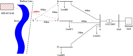
Figure 2: -ine diagram of the power system considered in part D of coursework 2.
6 Planning for Load Growth (Part D of Coursework 2)
There is an anticipated significant increase in load demand near Bus C. To address this challenge, three network expansion options are proposed (see Figure 2), each with distinct technical, environmental, and economic implications:
· Option 1: The first option, as studied in the lab from a technical point of view, involves constructing a new fossil fuel power station at Bus E. This solution offers proximity to existing infrastructure and reliable power delivery, but raises concerns regarding environmental impact and long-term sustainability.
· Option 2: The second option proposes supplying the additional load from the 400-kV transmission grid. This would require building a 100-kilometre dedicated transmission line and installing a step-down transformer near Bus C. While this approach leverages existing high-voltage infrastructure and may provide reliable electricity to the industrial site, it involves substantial capital investment and land use considerations, particularly in the vicinity of the river.
· Option 3: The third option introduces a renewable energy solution: the development of a wind farm of appropriate capacity on a farmland close to Bus C, supported by a Battery Energy Storage System (BESS) to manage the intermittency and volatility of wind generation. This option connects to the existing distribution system and reduces carbon emissions, but also requires careful planning to ensure reliability, community acceptance, and economic viability.
Brief Instructions for Individual Work:
Group members remain the same for Software and Hardware Lab sessions. Your group must select five academic references (book chapters, standards, government reports, peer-reviewed journal articles, or conference papers). This shared list ensures all students start from a common evidence base.
In the coursework, you will explain your own preferred solution (which may be similar or different from that of other group members) and expand on its implications using technical arguments, ethical reasoning, and sustainability perspectives. This should be based on the collectively selected references, and group discussions held during the Software Lab session and afterwards. From the release of Coursework 2 onward, however, all work is individual and will be assessed independently.
2025-12-05
Distribution Network Reinforcement, Expansion and (N-1) Security Analysis in PowerFactory