ELEC3575 Electric Power Systems Coursework 2
Hello, dear friend, you can consult us at any time if you have any questions, add WeChat: daixieit
ELEC3575
Electric Power Systems
Coursework 2, December 2025
Software/Calculator instructions:
· You are allowed to use MATLAB, calculator or a computer calculator in this assessment.
Dictionary instructions:
· You are allowed to use your own dictionary in this assessment and/or the Spell Checker facility on your computer. You are not marked on spelling, punctuation or grammar in this assessment.
Assessment Information:
· There are 13 pages and four parts to this online assessment.
· You will have 7 days to complete the assessment.
· You are recommended to take a maximum of 6 hours within the time available to complete the assessment.
· This assessment is worth 70% of the overall module mark.
· The deadline for submission of your assessment is 14:00, UK time, 9/12/2025.
· Please submit your assessment to the ‘Submit Your Work’ area in the module’s Minerva page.
· Please include your Student Identification Number (SID) in the title of your submission.
· Please include your Student ID Number and the Module Code at the top of each page of your submission.
· If there is anything that needs clarification or you have any problems, please email [email protected] and copy in [email protected] and we will respond to you as quickly as possible within normal working hours UK time (9:00-17:00 hours, Monday-Friday).
· You must not discuss or share the content of or answers to this assessment, with any fellow students, any staff or other contacts outside the school or the University’s professional services. School contacts available to you will be detailed in the bullet point above.
Submission instructions:
· You must submit your assignment to the ‘submit your work’ area in the module’s Minerva page no later than the submission deadline of 14:00, UK time, 9 of December 2025.
· You should receive an e-mail receipt from the Turnitin system to confirm that your work has been properly submitted.
This coursework has four main parts (Parts A, B, C and D). There are some tasks you need to do, before starting to work on the question. These tasks are just enabling steps you need to take and there is no need for you to show or explain how you conducted the tasks.
a. To answer Questions 1-a to 1-e, you will need to carry out Tasks T1-T6.
b. To answer Questions 2-a to 2-e you are required to complete Tasks T7-T11.
c. To answer Part D, you must have carried out Task 12, discussed the three options within your group and chosen up to 5 references.
You must submit your Responses to the four parts in one single document via the link provided on the module’s Minerva page.
In summary, what you are expected to do for this coursework is:
Part A: Run AC power flow on a meshed power system modelled in MATLAB/Simulink and discuss the results. Answer Questions 1-a to 1-e.
Part B: Perform DC power flow on this power system in MATLAB/M-file and compare the results with the AC power flow results. Answer Questions 2-a to 2-e.
Part C: Perform Backward-Forward Sweep Method for a radial system and answer some fundamental questions (Questions 3-a to 3-f) based on what we have discussed in the lectures, screencasts and the handouts given to you.
Part D: Preform planning for load growth, and compare options using technical, ethical, and sustainability analysis.
Preamble (PL1): In this coursework, the active power of the load at bus 1 depends on your student ID number. In Parts A and B, PL1 is set to be 40+XX/5 where XX are the last two digits of your student ID number. You should round the value of PL1 to
Your own PL1 value: PL1=40+XX/5=
the closest integer number.
For example, if your student ID number is 200123065, you must use the following PL1 value to attempt this exam:
PL1= 40+65/5= 53 MW (rounded to the closest integer)
Part A: AC Power Flow for a Meshed Power System
For Part A, you need to run an AC power flow on the power system shown in Figure 1 (as per Tasks T1-T7) and answer Questions 1-a to 1-e.
Tasks T1-T7 and Questions 1-a to 1-e:
Task T1: Download the “ELEC3575_Power_Systems_Coursework2.slx” file from Minerva and save it on your local PC.
Task T2: You can read Power Flow-Matlab.docx document provided on how to open/run the file using an installed or online MATLAB. Then find “MATLAB” in the program manager of Windows and start it (or use the online version as explained).
Task T3: Open the downloaded “.slx” file with MATLAB.
Task T4: Now you should see a network in the Simulink workspace. The network represents the 110-kV system shown in Figure 1.
Task T5: Double click on the lines to check if they are set with the parameters listed in Table 1.
Task T6: Ensure the demand and generation at all buses match those listed in Table 2. You must replace the active power of load at bus 1 with PL1 you calculated based on your student ID. In the opened dialogue box, you may check the bus type in tab “load flow”.
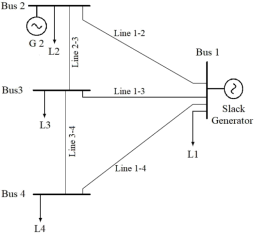
Figure 1. 110 kV power system under study.
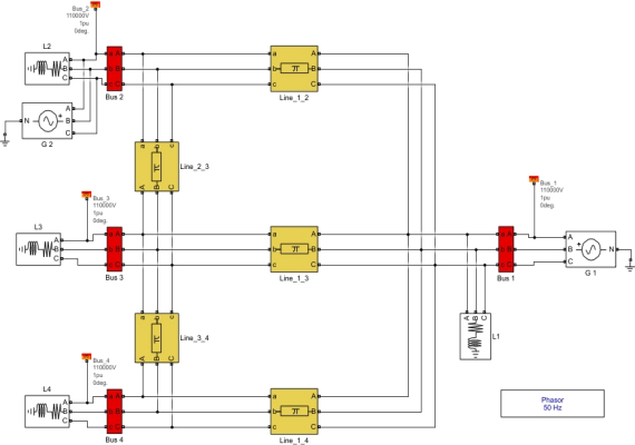
Figure 2. Simulink schematic of the power system under study.
Table 1: Line characteristics.
|
Line |
Length [km] |
Resistance (R′) |
Inductance (L′) [mH/km] |
Capacitance (C′) [µF/km] |
|
Line 1-2 |
160 |
0.016 |
1.30 |
0.009 |
|
Line 1-3 |
150 |
|||
|
Line 1-4 |
100 |
|||
|
Line 2-3 |
110 |
|||
|
Line 3-4 |
75 |
Table 2: Load and generation data.
|
Bus No. |
Load |
Generation |
Bus Type |
|
|
P (MW) |
Q (MVAR) |
P (MW) |
||
|
1 |
PL1* |
18 |
** |
Slack bus |
|
2 |
90 |
20 |
120 *** |
PV |
|
3 |
40 |
18 |
0 |
PQ |
|
4 |
40 |
10 |
0 |
PQ |
* The value of PL1 is student specific and is calculated as explained in the Preamble section on page 2.
** Note that the exact amount of P for the slack generator is determined by AC power flow.
*** Bus 2 is a PV bus, and the generator at that bus is set to maintain the voltage of bus 2 at 0.98 pu (V2= 0.98 pu).
Task T7: To run a load flow for the system, double-click on the box “powergui” and then go into tab “Apps” and select “Load Flow Analyzer”. A window for the power flow results will pop-up, then click on the button “Compute”. The power flow results are shown in the last five columns of the window, similar to what you can see in Figure 3.

Figure 3. Sample power flow results shown in the dialogue box.
Note: Sample results shown in Figure 3 are inaccurate and are used to give you an idea of what to expect to achieve after running Task T7.
Questions 1-a to 1-e (20 Marks Overall)
Question 1-a) State what your own PL1 is and check if the voltage magnitudes at different buses are within the acceptable range (i.e., 5% of the nominal voltage). [2 marks]
Question 1-b) Manually calculate the active and reactive power flows through each line in MW/MVar. As you know, the power flows from the sending- and receiving- end of each line are not necessarily identical and are to be calculated and reported.
We model each transmission line simply by a series reactance. In this way, the active/reactive power flow from bus i to bus j can be approximated by
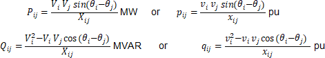
where Vi is the voltage phasor of bus i in kV, Xij is the reactance of the line connecting bus i to bus j in Ohms.
To calculate these, you may import the required data into an m-file and calculate active and reactive power transferred through each line using a code you write. Note that you will need these power flows through lines for comparison studies later in Question 8. [5 marks]
Question 1-c) What is the sum of the active powers generated by G1 and G2 and is this sum greater than, equal to or smaller than the sum of active powers consumed by the loads? Explain what this difference implies. [3 marks]
Question 1-d) Based on our discussion in ELEC3575, name two options as the initial guess for solving the AC power flow problem using iterative methods such as Newton-Raphson. Based on what we have discussed in the lectures, explain why these options can be considered appropriate. [4 marks]
Question 1-e) Explain the “N-1” security criterion. Detail how you can check the N-1 security criterion for the power system shown in Figure 1, based on the assumptions we made in ELEC3575 regarding power systems. To this end, you need to state what study is required to be carried out and for how many times. Which variables will you need to check every time this study is performed? [6 marks]
Part B: DC Power Flow for a Meshed Power System
For this part, you must use the data listed in Tables 1 and 2. It is recommended that you write an M-file to perform the DC power flow calculations (begin by opening the “Line_Data.m” file). Also, make sure to reset the load and generation values in the Simulink file so that they match those given in Table 2.
Tasks T8-T11 and Questions 2-a to 2-e:
For your convenience, the line parameters are already saved in a matrix named “Line_Data.mat”. You are supposed to add your code to this m-file such that it does the DC power flow calculations on the power system under study. Your m-file must contain the sections as explained in Task T8 to Task T11.
Task T8: Calculate the line reactance in Ohms. Ignore R′ and C′, and G′ of the lines and compute the series reactance of the line considering their “length”, per unit length “inductance”, and the system nominal frequency (50 Hz).
Task T9: Calculate the line reactance in pu. Use a base voltage (110 kV) and a base apparent power (100 MVA) to calculate the base impedance, then convert the line reactances to their per-unit values.
Task T10: Form the nodal admittance matrix including all transmission lines. You may find useful guidance in the lecture notes about this. Eliminate the row and column corresponding to bus 1.
Task T11: Form the vector of net active power injections. The required data are included in Table 2. Do not forget to convert Active Power generations to per-unit values. Do not forget that you need to eliminate the reference bus from this vector.
Questions 2-a to 2-e (20 Marks Overall)
Question 2-a) Manually calculate the phase angles of all buses.
Hint: You should do this by multiplying the inverse of the reduced nodal admittance matrix by the vector of net active power injections (θ = A-1PDC). Note that phase angles calculated from this will be in radians. [3 marks]
Question 2-b) Using the formulas below, calculate the active power flows through the lines (from sending end and receiving ends of each line).
Hint: The active power flow from bus i to bus j can be approximated as follows in DC power flow calculations:
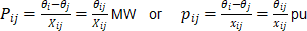
where θi is the voltage phase angle at bus i in radians, and Xij is the reactance of the line connecting bus i to bus j in Ohms. [5 marks]
Question 2-c) Compare the DC power flow result with that of AC power flow. You need to compare voltage phase angles of all buses and the active power flow of all lines obtained by DC power flow with your findings in Part A (AC power flow results). Explain the reason for their difference. Which one is more reliable, and why? [3 marks]
Question 2-d) Double click on load L3 at bus 3 and set its “Inductive reactive power QL” to 100 MVAR (i.e. 100e6). Then, run an AC power flow and examine whether the power calculation converges. Does DC power flow calculation change for this new condition? Compare DC power flow result with that of AC power flow. Is DC power flow still accurate and acceptable? Why? [3 marks]
Question 2-e) Double click on load L3 at bus 3 and set its “Inductive reactive power QL” to 200 MVAR (i.e. 200e6). Then, run an AC power flow. Does the power calculation converge? Can you rely on DC power flow results in this case? Why?
Hint: You will need to use the concept of P-V curves to justify your answer to the “why” part of this question. [6 marks]
Part C: Power Flow on a Radial System
Figure 4 presents the single-line diagram of a radial power system representing one track of Network Rail between two cities. The system parameters, including line impedances, train power demands, and the voltage at the feeder station, are provided for a specific moment in time. Impedances are expressed in per-unit. To express train powers in per-unit, use a base power of PB = 10MW.
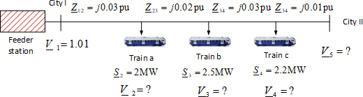
Figure 4. The radial power system representing one track of Network Rail between two cities.
Questions 3-a to 3-f (20 Marks Overall)
Question 3-a) Explain why it is essential to maintain a consistent base power across the entire system when using the per-unit method. Refer to the principles discussed in ELEC3575 to support your explanation. [2 marks]
Question 3-c) Describe the Backward-Forward Sweep algorithm used for load flow analysis in radial systems. Your explanation should include:
· How branch currents and node voltages are estimated in each iteration.
· How convergence is determined. [3 marks]
Question 3-d) Based on our discussions in ELEC3575, compare the Backward-Forward Sweep Method with the Newton-Raphson Method in terms of:
· Computational efficiency.
· Suitability for radial networks. [2 marks]
Question 3-e) To improve train operations, a small Battery Energy Storage System (BESS) is proposed at city II to supply the overall load from both ends of the track. Identify the bus type (Slack, PV, or PQ) that station B would represent in load flow studies after the BESS is added. Justify your choice. [4 marks]
Question 3-f) Assume the BESS operates at unity power factor, and all train loads also have unity power factor. Discuss how the addition of the BESS would affect the voltage profile along the railway track and system losses in general. [5 marks]
Part D: Planning for Load Growth
In the context and continuation of the Software Lab, it is assumed that there will be a significant increase in load demand near Bus C (shown in Figure 5). To address this challenge, three network expansion options were proposed, each with distinct technical, environmental, and economic implications. More details can be found from the software lab instruction handout.
The first option, previously studied in the lab from a technical point of view, involves constructing a new fossil fuel power station at Bus E. This solution offers proximity to existing infrastructure and reliable power delivery, but raises concerns regarding environmental impact and long-term sustainability.
The second option proposes supplying the additional load from the 400-kV transmission grid. This would require building a 100-kilometre dedicated transmission line and installing a step-down transformer near Bus C. While this approach leverages existing high-voltage infrastructure and may provide highly reliable electricity to the industrial site, it involves substantial capital investment and land use considerations, particularly in the vicinity of the river.
The third option introduces a renewable energy solution: the development of a wind farm of appropriate capacity on a farmland close to Bus C, supported by a Battery Energy Storage System (BESS) to manage the intermittency and volatility of wind generation. This option connects to the existing distribution system and reduces carbon emissions, but also requires careful planning to ensure reliability, community acceptance, and economic viability.
These three options form the basis of Part D of this coursework. You have been asked to collaboratively assess the merits and drawbacks of each option using appropriate references discussed during your group work. You must now explain your individual preferred solution and expand on its implications through technical analysis, ethical reasoning, and sustainability perspectives.
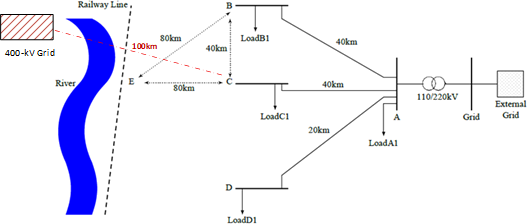
Figure 5. Single line diagram of the power system considered in part D.
Part D (40 Marks Overall and Maximum Length: 1,000 Words)
Instructions for Individual Work:
This section is based on the group discussions held during the Software Lab session and afterwards (up until the release of Coursework 2) between your team members. During these discussions, students collaboratively explored three energy supply options to address increased load demand near Bus C. From the release of the coursework onward, all work is entirely individual and will be assessed independently. Each student must submit a personal report that includes the following components:
Task 12. Group Context and Reference List (not included in the wordcount)
Begin your report by listing the names of your group members from the Software Lab session. Then, provide a list of five references that were selected collectively during your group discussion. These references must be limited to academic sources such as book chapters, government reports, peer-reviewed journal articles, or conference papers. This shared reference list ensures that all students begin their individual
Important: For students who missed the Software Lab session and did not participate in any group discussions, it is important to state this clearly in Part D of your submission. You should individually select and reference your 5 own suitable academic sources. For the “Group Discussion Summary (≈200 words)” section below, you should base your individual initial understanding on the discussions held throughout ELEC3575, as well as the material covered in class using the “Planning for Load Growth.pptx” slides, before developing your analysis.
analysis from a common foundation of evidence and rationale.
1. Group Discussion Summary (≈200 words)
Provide a concise summary of the problem statement and the key points discussed during your group session. This summary must be written in your own words and should reflect your personal understanding and interpretation of the group’s evaluation. Avoid copying or paraphrasing the group summary directly. Instead, demonstrate how you have internalised the discussion and framed the problem independently, including the rationale behind comparing the three expansion options.
2. Individual Preferred Option and Rationale (≈200 words)
Clearly state which of the three proposed energy supply options you personally prefer. Justify your choice using a combination of technical reasoning, environmental impact analysis, economic considerations, and social implications. While you are encouraged to draw on the shared references and lecture materials from ELEC3575, your rationale must reflect your individual perspective and critical thinking.
3. Copilot Interaction and Evolving Rationale (≈200 words)
Engage interactively with Copilot to further explore and refine your rationale. Use this dialogue to challenge your assumptions, explore alternative viewpoints, and introduce new angles of analysis. Summarise the key insights gained from this interaction, highlighting how your reasoning evolved or was reinforced. Pay particular attention to moments where you successfully defended your position using concepts and materials discussed in ELEC3575. This section should demonstrate how Copilot contributed to your deeper understanding of the chosen option.
4. Ethical Justification (≈200 words)
Apply at least two ethical lenses to justify your preferred option. Acceptable frameworks include utilitarianism, rights-based ethics, justice-oriented approaches, and intergenerational equity. Discuss how these ethical perspectives influence your evaluation and support your stance. This section should show your ability to integrate ethical reasoning into technical decision-making and reflect on broader societal impacts.
5. Conclusion and Reflection (≈200 words)
Conclude your report with a reflective summary of the trade-offs involved in your chosen option. Briefly revisit what you learned through your Copilot interaction and ethical analysis, and explain how these insights shaped your final position. This section should demonstrate critical thinking, personal growth, and an awareness of the complexities inherent in energy system decision-making.
Expected Structure
At the beginning of your response to Part D, clearly state your word count (from the start of your Group Discussion Summary to the end of your Conclusion and Reflection). The total must not exceed 1,000 words.
Part D Rubric
Total Marks: 40 | Maximum Length: 1,000 Words
|
Section |
Marks |
Assessment Criteria |
|
1. Group Discussion Summary |
8 |
Demonstrates ability to interpret and summarise complex engineering discussions. Shows understanding of the problem context and rationale for comparing options. Uses own words to reflect group reasoning. |
|
2. Individual Preferred Option and Rationale |
8 |
Selects a preferred solution and justifies it using engineering principles. Evaluates technical feasibility, environmental impact, economic viability, and social relevance. Demonstrates independent judgement and application of ELEC3575 concepts. |
|
3. Copilot Interaction and Evolving Rationale |
8 |
Engages critically with Copilot to explore assumptions, alternatives, and trade-offs. Documents how reasoning evolved or was reinforced. Applies systems thinking and course knowledge to defend conclusions. |
|
4. Ethical Justification |
8 |
Applies at least two ethical frameworks to evaluate the chosen solution. Justifies decisions with reference to societal, intergenerational, and justice-oriented considerations. Demonstrates ethical awareness in engineering contexts. |
|
5. Conclusion and Reflection |
8 |
Reflects on trade-offs, ethical reasoning, and insights gained. Demonstrates critical thinking, personal learning, and awareness of complexity in power system planning. |
2025-12-05