ENGR20004 Engineering Mechanics 2022
Hello, dear friend, you can consult us at any time if you have any questions, add WeChat: daixieit
ENGR20004 Engineering Mechanics
Assignment 1 – Shear Force, Bending Moment and Axial Loading
Instructions
A short oral test (5 marks) will be conducted before your experiments. You are expected to read the handouts and watch lab videos in advance. Demonstrators will ask you simple questions related to ex- periments. If you fail to answer, you will be asked to return to your desk and review the lab materials again.
Reporting
Each group of 3 is to electronically submit two files to LMS:
1. Report (in PDF format, no more than 8 pages, excluding appendix), and
2. MATLAB script (or m-file) for Question 4. No marks will be awarded for Question 4 if you do not submit a separate m-file for the function. This also applies to late submissions.
3. The total marks of this assignment is 55 (Report: 50 marks + Oral test: 5 marks).
GUNT Experiment
During your lab session, please follow the experiment procedures and record load-cell readings. You can evaluate your experiment results after your lab session.
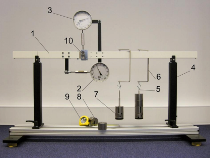
Figure 1: Experiment components are: 1–Beam, 2–Load cell for bending moment with pivot, 3–Load cell for shear force, 4–Support with roller bearings, 5–Weight holder, dead weight 1 N, 6–Load hanger, 7–Weight 1 N, 8–Weight 5 N, 9–Measuring tape 10–Joint. The beam has to be supported 0.8 m apart.
Question 1 - Concentrated single load (15 marks)
Experiment Procedures Erect experimentation set-up as shown in Figure 1 (without the weights on for now - that is to show you how to hang them on later), then follow the steps below.
(i) Measure the distance between the joint and the left support.
(ii) Take the load-cell readings and note down values.
(iii) Case 1: Use a load hanger to position a 20 N load 0.3 m from the right support.
(iv) Take readings from both load-cells again and note down values. The shear force is given by the
change in readings after applying the load. The bending moment is given by the change in readings multiplied by the moment arm (0.1 m).
(v) Repeat experiment for:
Case 2: Use load hanger to position a 20 N load 0.15 m from the right support.
Experiment Evaluation Evaluate experiment results by including the following in the report:
Q1(a) Obtain the experimental bending moment and shear force for Case 1 and Case 2. Q1(b) Calculate the analytical bending moment and shear force Case 1 and Case 2. Q1(c) Calculate the percentage error between experimental and analytical results using

and justify whether the errors are acceptable. (Hint: what is the accuracy of the dial gauge?)
Question 2 - Concentrated double load (5 marks)
Experiment Procedures
(i) Take load-cell readings and note down values.
(ii) Use load hangers to position two 20 N loads on the beam at a distance of 0.15 m and 0.3 m from
the right support.
(iii) Take readings from both load-cells again and note down values.
Experiment Evaluation By applying the superposition principle to the analytical results obtained for Case 1 and Case 2, calculate the analytical bending moment and shear force (You must apply the superposition principle). Then, compare those values with the experimental results for the double load.
Question 3 - Moving concentrated double load (10 marks)
Experiment Procedures
(i) Take load-cell readings and note down values.
(ii) Use load hangers to position a 5 N load and a 20 N load on the beam 0.15 m apart. Only the white
beam sections are allowed to take loading, and do not position the load hanger at a location where the bending moment load cell is obstructing.
(iii) Move both loads until you get the maximum reading from the bending moment load-cell. Note
down the distance of the two loads from the right support.
Experiment Evaluation Evaluate experiment results by including the following in the report:
Q3(a) Obtain the experimental bending moment and shear force.
Q3(b) Using the worst-case load positions identified experimentally, calculate the analytical bending moment under this configuration to compare with the experimental result. Comment on any dif- ferences between the two.
MATLAB
Question 4 (5 marks)
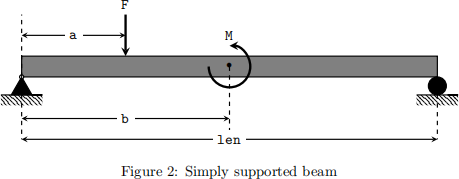
Write a MATLAB function to plot (a) the shear force diagram (SFD) and (b) the bending moment diagram (BMD) for a beam with one concentrated point load and an applied moment as shown in Figure 2. You should clearly specify your sign convention and axis origin in your report. The robustness of the function will be tested.
Use the following code as the function header. (Hint: you can use the stairs function to plot the SFD)
|
function SFD_n_BMD(len,F,a,M,b) % Inputs : % len : Beam length [m]; % F : Concentrated point load [N]; % a : Distance of point load from the left [m] % M : Applied moment [Nm]; % b : Distance of applied moment from the left [m] %--STEP 1: CALCULATE REACTIONS R-- %--STEP 2: COMPUTE SF and BM AT SUPPORTS AND LOADING-- %--STEP 3: PLOT SFD and BMD-- end |
Include your MATLAB code as a separate m-file, together with your report. In your report, include a plot for the following input:
|
>> SFD_n_BMD(12,200,3,300,6) |
Since the assessment for Question 4 is based on your submitted m-file, no marks will be awarded for Question 4 if you do not submit a separate m-file for the function. This also applies for late submissions.
Truss Experiment
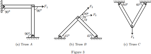
For this experiment, you will be analysing three different truss systems A, B and C illustrated in Figure 3. The truss systems will be modelled by Pixie frames that have been set up for you. Each truss member of the Pixie frame has an internal spring with a spring stiffness constant k = 1.94 N/mm which allows the member to extend or compress when an axial load is applied. A window is cut into each member to provide visual access to an internal rod – the displacement of the tip of this rod (see Figure 4) will be used to measure the extension or compression of the truss. Using the value of the displacement, we can then approximate the internal forces experienced by each truss member using Hooke’s Law.
The aim for this experiment is to:
1. Measure and compute the internal forces of the trusses A, B and C under different loading scenarios.
2. Compute the analytical internal forces of the trusses A, B and C.
3. Compare the measured and analytical forces and discuss the differences, if any.
Equipment
1. Pixie frames.
2. Pulleys, strings and buckets to apply the required force, F1 , F2 , F3 and F4 .
3. Loads with mass of approximately 205 g (to be verified) in total.
4. Digital calliper, protractor.
5. Camera (or a smartphone with a high-resolution in-built camera).
Experiment Procedures
1. Using a digital calliper, measure the full internal separation of the window. This will be used in the MATLAB function extractLengths.m for calibration.
2. Using the protractor, measure and verify the angle at which the force is acting on the truss. This is especially important in order to determine the angle θ for the force F3 , shown in figure 3(b).
3. Take a photo of the window before applying the load.
4. Load the bucket with the weights provided to apply the force.
5. Take a photo of the window after the load has been applied.
Question 5 (5 mark)
For Truss A, calculate the analytical internal forces in the two members when the horizontal force F1 is applied. Then, using the images taken during experiment and the spring stiffness constant k for each member, estimate the internal forces in Truss A. Assume that k is the same for all members. Does Truss A have any zero-force members? Provide comments, if any.
Question 6 (5 marks)
For Truss B, calculate the analytical internal forces for the two different loading scenarios; first only for F2 , then only for F3 . Next, repeat the earlier steps (for Truss A) and estimate the internal force in each member of Truss B for both loading scenarios. Compare and comment on your analytical and experimental results, and also comment on any zero-force members in Truss B .
Question 7 (5 marks)
Repeat the steps for Truss C with a downward load F4 . Again, compare and comment on your analytical and experimental results.
Additional Notes
Taking the Photo

When taking the photos, it is important to orient your camera parallel to the window in order to minimise distortion of the image. An example of a poorly oriented photo is shown in Figure 4(b) where a section of the truss is visible (illustrated by the red arrows). A slightly better photo is shown in Figure 4(a). Once all the photos have been taken, you will be using the provided MATLAB function extractLengths.m to determine the extension of each of the members. A how-to video for the MATLAB function will be provided on LMS, which explains how to extract the displacement of the internal metal rods from the windows.
Acknowledgements The Pixie frames truss setup is part of the TechnoLab – Basic Mechanics Home-
Lab Series.
Appendix
How the GUNT experiment allows you to determine the bending moment at the hinge
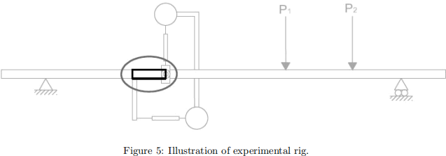
Consider the free body diagram of the bolded section of the experiment rig as shown above in Figure 5. Assuming a perfectly continuous beam (as the experimental beam is idealized as during analytical analysis) we would expect the shear force and moment at either end of the section to be as shown below (Figure 6a). However the measurement of the bending moment and shear force at a particular point on a real continuous beam is not a straight forward exercise.
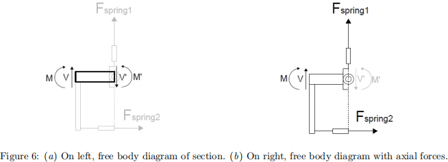
Instead, for the purpose of this experiment, we approximate the continuous beam using a hinge joint and a set of gauges. This set up behaves as a continuous beam and allows us to measure the bending moment and shear force at the hinge position. This is possible as a result of the axial forces generated in each of the gauges (shown in figure 6b).
As you observe the experimental set up, you will see that it is in static equilibrium. Without the gauges, this would not be the case as the beam would rotate and displace at the hinge. The gauges are installed in a manner such that the axial forces that develop within the gauges, e.g. Fspring1 and Fspring2 , keep the beam horizontal.
Given the experimental set up approximates a continuous beam, the bending moment at the hinge position, M/ , can be determined by taking the moment due to the horizontal force Fspring2 (as indicated by the lower load cell) about the hinge position by multiplying it by the moment arm (0.1m), i.e. M/ = Fspring2 × 0.1. The shear force, V/ , can simply be read off of the upper load cell, i.e. V/ = Fspring1 .
2022-01-13
Assignment 1 – Shear Force, Bending Moment and Axial Loading