FIT1047 Introduction to computer systems, networks and security - S1 2025 Assignment 2
Hello, dear friend, you can consult us at any time if you have any questions, add WeChat: daixieit
FIT1047 Introduction to computer systems, networks and security - S1 2025
Assignment 2 – MARIE Programming (v1.3 22/03/2025)
Purpose
This assignment is mainly about programming in the MARIE assembly language. This will allow students to demonstrate their comprehension of the fundamental ways a processor works. In addition, basic knowledge about processes, memory and files is assessed in an in-class test.
The assignment relates to Unit Learning Outcomes 2, 3 and 4.
Your tasks
Part 1: Submit your reflections. See details below.
Part 2: Disassemble and add comments to a MARIE program.
Part 3: Write a MARIE program that can display bitmap numbers.
Part 4: In-class in-person test and interview (week 8 applied session).
Value
25% of your total marks for the unit.
The assignment is marked out of 60 marks.
Word Limit
See individual instructions
Due Date
Part 1–3: 11:55 PM Friday 11 April 2025
Part 4: Interview and test conducted during your official allocated
Applied Session in Week 8
Submission
● Via Moodle Assignment Submission.
● DRAFT submissions are not assessed. Re-check your submission in Moodle.
● Turnitin and MOSS will be used for similarity checking of all submissions. Ignore Turnitin warnings or error messages for .mas files or other non-document files.
● DRAFT upload confirmation email from Turnitin is not a submission. You must click the submit button to accept terms and conditions in Moodle.
● This is an individual assignment (group work is not permitted).
● In this assessment, you must not use generative artificial intelligence (AI) to generate any materials or content in relation to the assessment task.
● You will need to explain and extend your code in an interview. (Part 4)
Assessment Criteria
Part 1 is assessed based on relevance of the submission to the unit.
Part 2 is assessed based on correctness of the code and the labels/comments.
Part 3 is assessed based on correctness of the code, as well as the documentation/comments.
Part 4 is assessed based on the understanding of the code you have written. See instructions for details.
Late Penalties
5% deduction per calendar day or part thereof for up to one week.
Submissions more than 7 calendar days after the due date will receive a mark of zero (0) and no assessment feedback will be provided.
Support Resources
See Moodle Assessment page
Feedback
Feedback will be provided on student work via:
general cohort performance
specific student feedback ten working days post submission
INSTRUCTIONS
This assignment has four parts. Make sure you read the instructions carefully.
For Part 1, collect your reflections from each week’s Ed Lesson and create a single PDF document. You can simply copy/paste your reflections, but please add headings for each week. A template is available on Moodle. Submit the PDF through the Moodle Assignment activity.
For Part 2 and 3, you need to submit files through the Moodle Assignment activity. Each part requires the submission of one or two .mas files inside a .zip file.
You may see the following error message from Turnitin. You can ignore this error message!
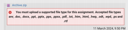
Part 4 is an in-class interview and test during your allocated Applied Class in Week 8. Instructions will be available in Moodle and communicated via an announcement post.
Part 1: Reflection (Not marked, but cap on overall mark applies)
Complete your reflection activities for Week 4 to Week 6 in the corresponding Ed Lesson and copy/paste them into a PDF file. Write at least 100 words for each week (relevant and meaningful to the specific week).
Failure to submit all relevant reflections (missing all submissions or incomplete submissions) will result in your Assignment 2 having a maximum mark of 50%. For example, if the overall combined mark is 31/60, it will be scaled to 30/60. If the overall combined mark is 28/60 then it will remain as 28/60.
You may use this template:
https://docs.google.com/document/d/18UIEJQeyarYW1pl8oDEaf--ubCdJ5LDf-9_jSLbGxrE/edi t?usp=sharing to write down your reflections.
Part 2: MARIE Disassembly (20 marks total)
Follow the link on Moodle to access your personalised MARIE memory screenshot for this task.
Important: Your memory screenshot is different from the one other students are working on. Only download the file while you are correctly logged into Moodle with your own student account.
Task 1: Disassemble the memory (8 marks)
Based on the memory contents, recreate the MARIE program that corresponds to your personalised memory screenshot. This is called “disassembling” the machine code, since it is the opposite operation of “assembling” the MARIE code into the binary memory contents.
For each memory cell, decode the instruction and (if applicable) the address that the memory cell is encoding. You can make the following assumptions:
- There is exactly one Halt instruction in the code
- Every memory location after the Halt instruction contains data
- Any memory location that contains the value 0 is data (even before the Halt instruction)
Here is an example of a memory screenshot and the corresponding decoded MARIE program:

Disassembled program:
Input
Add 005
Output
Jump 000
Halt
DEC 10
Note: You need to decode the actual instructions. E.g. for the first memory location, HEX 5000 would not be a valid answer. The contents of all memory that follows the Halt instruction is considered to be data. Therefore, DEC 10 is the correct decoding of location 5 (instead of JnS 00A), and HEX 00A would also be correct. You don’t need to list all the locations containing zeros starting from address 006 (these will be filled with zeros by the assembler anyway).
Tip: You can verify that your disassembled code is correct by entering it into the MARIE simulator, assembling it and comparing the memory contents to the screenshot you started from.
Task 2: Add labels (5 marks)
Now update the program you decoded in Task 2.1. Remove all hard-coded memory addresses by adding labels to replace all memory locations that are used as addresses in the program instructions. Labels should have meaningful names in the context of what the program does (i.e., not just A, B, C). For the example above, this could result in the following program:
MainLoop, Input
Add Ten
Output
Jump MainLoop
Halt
Ten, DEC 10
Hints: All data used by the code can be interpreted as integer numbers, so it’s probably best to use the Decimal output mode. Run the code and observe the output. Ask yourself how the output relates to the given data. Use the step functionality in the MARIE simulator to understand step by step what the code does. Which parts are subroutines? Which parts are loops? What do the SkipCond instructions do? How are the different data values used?
Task 3: Add comments (7 marks)
Comment the code based on your understanding of what it does. Comments should describe the function of the different parts. E.g., if you identify a subroutine in the code, add a comment at the start of the subroutine that describes what it does, and whether it takes any arguments.
For this part (Part 2), you need to submit a ZIP file containing a single .mas file containing your final code. If you attempted all three tasks, your .mas file should not contain three copies of the code - only submit the Task 3 code in that case (or only Task 2 if you did not attempt Task 3).
The Moodle submission activity for Part 2 contains a “quick check” function that you can use to check if your submission has the right structure.
Part 3: MARIE Programming (30 marks total)
In this task you will develop a MARIE application that paints characters on the screen. We will break it down into steps for you.
Each task requires you to write code and documentation. On Moodle, you will find a template for the code. Your submission must be based on this template, i.e., you must add implementations of your own subroutines into the template. The template already contains the main program that calls the subroutines.
Your code must contain readable comments and meaningful labels for your tutor / marker to understand the logic flow of your program (e.g. the purpose of a subroutine, Jump / SkipCond instruction etc.).
In-class interview (Part 4): You will be required to join an interview to demonstrate your code to your tutor during your applied session in week 8 (after the submission deadline).
Failure to demonstrate will lead to zero marks being awarded for the entire Part 3, regardless of your submission in Moodle. In addition, during the interview (Part 4), you will also need to answer further questions about your submitted code (see below for details).
Code similarity: We use tools such as MOSS and Turnitin to check for collaboration and copying between students. If you copy parts of your code from other students, or you let them copy parts of your code, this will result in a report to the Academic Integrity team. As a result, you may receive a penalty such as 0 marks for the entire assignment, 0 marks for the whole unit, or in severe cases (such as contract cheating), suspension or expulsion from Monash University.
Rubric: The marking rubric on Moodle provides details for the marking. A correctly working MARIE program that covers all tasks and is well documented will receive full marks.
Missing/incomplete documentation will result in a loss of up to ¼ of the task’s marks.
Introduction: Bit-mapped displays
So far, the only output capability we have seen in the MARIE system is using the Output instruction, which will print a single 16-bit value. Many computers of course are capable of displaying arbitrary graphics, often in high resolution and great colour depth. In the lectures on input/output systems, we have seen that one way to implement this is to map a certain location of the memory to an output device. I.e., writing to that memory location (using e.g. a Store instruction) causes the output to happen.
In the simplest form of graphics hardware, we can dedicate part of the RAM to be graphics memory. Each memory cell corresponds to a pixel on screen, and the value in the memory cell encodes the colour of the pixel. That way, we can create arbitrary graphics by simply writing values into the memory.
The MARIE simulator has a feature called Display, which you access from the list of tabs that also shows the output log, RTL log etc:
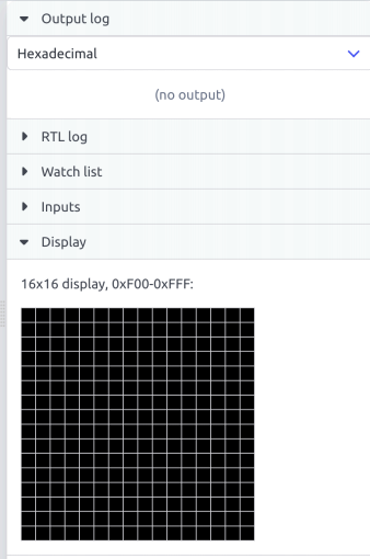
The display shows the memory from address F00 to address FFF as a 16x16 pixel screen. The value in the memory locations represents the colour of the pixels. We will only use the colours black, represented as 0, and white, represented as FFFF. When you start the MARIE simulator and assemble your code, the memory starting from location F00 is (usually) filled with zeroes, which means that the display is black. Let’s now change the contents of the memory using some Store instructions:
Load White
Store 0F80
Store 0F81
Store 0F82
Store 0F83
Halt
White, HEX FFFF
After running this program, the display will look like this:
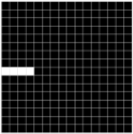
You can see that the first four pixels in the 9th row have now turned white.
Task 1: Clearing the display (4 marks)
Write a subroutine SubClearDisplay that uses a loop to turn all pixels in the graphics memory white. Remember that the graphics memory ranges from address 0F00 to address 0FFF, and that white pixels are represented by the value FFFF. Document your subroutine with comments.
Task 2: Painting a character (10 marks)
The template for this task contains data for bitmaps of the letters “a”-”z”, stored at the label Font. Each letter consists of 4x8 pixels of data. The first 4 words are the first row of pixels, the next 4 words are the second row, and so on. For example, the letter “a” is represented as
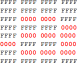
You can see the pattern here, the zeros “paint” the shape of the character “a” . We have highlighted the zeros in bold and red to make the pattern easier to see, but on the real display, the zeros would be black against the white background (FFFF).
Your task is to write a subroutine called SubPaintChar that paints a character into the graphics memory. The start of the subroutine needs to look like this:
PaintCharCharacter, HEX 0
PaintCharDisplay, HEX 0
SubPaintChar, HEX 0
In the PaintCharCharacter argument, we pass the address of the first pixel data in the font for the character we want to paint. In the PaintCharDisplay argument, we pass the address of the top-left corner where we want to start painting in the graphics memory. For example, to paint the character “c”, starting from the second pixel in the second row, we could use the following code:
Load FontAddr
Add SIXTYFOUR
Store PaintCharCharacter
Load Display22
Store PaintCharDisplay
JnS SubPaintChar
Halt
Display22, HEX 0F11
SIXTYFOUR, DEC 64
Note that the address 0F11 (label Display22) lies exactly 17 words after the start of the graphics memory. This means we’re skipping the first row (16 words) and the first pixel in the second row (1 word).
Here we use FontAddr, which refers to the first character (“a”), and then add decimal 64 to it, to get the address of the character “c” (each character uses 4x8=32 words of memory, so “c” starts at FontAddr + 64). For the other characters, we would have to add a corresponding offset into the font memory.
In order to paint a character in your subroutine, you can follow this “recipe” :
- Your subroutine should contain two nested loops.
- Each character contains 32 pixels, so you need to loop through those 32 pixels, load each one from the font definition and store it into the graphics memory. This is the outer loop of your subroutine.
- After each set of 4 pixels, you need to start in the next row of the graphics display. This means that if you were currently writing into graphics memory at address X, you now need to continue writing at address X plus the width of the display minus the width of a character. This is the inner loop of your subroutine.
- Once you have “copied” all 32 pixels from the font definition into the graphics memory, you can exit the subroutine.
Your subroutine needs to contain sufficient comments to enable someone else (like the person marking your assignment) to understand the purpose of each line of your code.
Task 3: Writing a string (12 marks)
Your final task is to implement a subroutine SubPaintString that clears the screen and then writes a string of characters to the display, one at a time. Each character of the string is painted using the subroutines developed in the previous tasks. After each character has been painted, you need to clear the screen again and then paint the next character.
A string of characters is represented in memory as consecutive locations, each containing an ASCII code of a character. The end of the string is marked by a memory location containing the value zero. The template contains the example string “marie” .
The starting address for the string of characters is passed to the subroutine in the AC register.
The string can be painted anywhere on the display you like.
You will notice that it would be nice for each character to remain visible for a second or so before the next character is painted. Think of a way you can achieve this. Document how you achieved this in the code comments.
A sample output video for this part is provided for your reference on Moodle.
For this part (Part 3), you need to submit a ZIP file containing the .mas file with the code for all subroutines, based on the template. Do not submit multiple .mas files!
Task 4: Be creative (4 marks, only available if Tasks 1-3 are complete and correct)
For the final task, think about creative ways to use the code you developed for Tasks 1-3. For example, you could make the text scroll or jump across the display, have some fun with colours, or any other idea you would like to implement. This task will be marked based on creativity and technical difficulty.
Only work on this task when you have completed Tasks 1-3. You will not be marked for Task 4 if the code you submit for Tasks 1-3 is incomplete or incorrect. Submit a separate (self-contained) .mas file for this part, inside the same ZIP file that contains your submission for Tasks 1-3.
Part 4: In-class test and interview (10 marks total)
You need to demonstrate the code you submitted for Part 3 Task 1–3 to your tutor in an in-class in-person interview (to be conducted during your official allocated Applied session in Week 8) after the submission deadline. Failure to explain how your code works will result in 0 points for the individual tasks that you cannot demonstrate.
In addition, you will be asked questions about the following topics:
- Demonstrate how to access a list of processes and applications on your computer.
- Answer questions about processes, memory and files as covered in the lectures.
- Modify your MARIE code in certain ways to make it behave differently.
- Explain how the MARIE concepts work that you were required to use for the individual tasks.
These additional questions add up to 10 points for this part.
Failure to attend the interview will result in 0 points for the entire Part 3 and Part 4, regardless of your submission in Moodle.
2025-09-19
MARIE Programming