Small-Scale Engine 2025
Hello, dear friend, you can consult us at any time if you have any questions, add WeChat: daixieit
DEPARTMENT OF MECHANICAL ENGINEERING
Small-Scale Engine
Mechanical Design A Supplementary Project 2025
PROJECT BRIEF
You are provided with the design of a single cylinder model aircraft engine. An image is shown in Figure 1. The engine generates 80 Watts of power with a shaft speed of 12,000 rpm. The combined force (inertia and the force from combustion) generated at the crank pin is 300 N. You are tasked with undertaking a review of the detailed design of the conceptual engine.
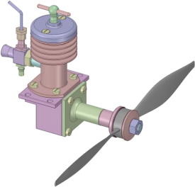
Figure 1 The single cylinder model aircraft engine
[supplied as an .stp file on Canvas for import to your chosen software]
SUBMISSION DETAILS
• The assignment will be submitted through Canvas.
• Submission deadline is Monday 11th August at 2pm (UK time)
• Any work submitted late will receive a penalty of 5% per working day.
• If you are unclear about any aspect of electronic submission or submission in general, you should seek advice well in advance of the assignment deadline.
• The report should be word processed in suitable font, size 12, with a minimum
line spacing of 1 times and written in English. This includes figure/table captions. The report has a maximum page limit of 16 pages (all sections unless stated).
• Your report should have a cover page. The following is required in this specific
order or 10% reduction in assignment mark will be applied. Module title,
Department (of Mechanical Engineering), Group number, and ID number, Report title, Date of submission.
• Appendices are not allowed.
• Immediately following the cover page, a completed University of Birmingham Assessment and Student Template should be provided. Details for this are provided in Appendix A.
• Immediately following the completed University of Birmingham Assessment and Student Template, a completed report writing checklist should be included.
Details for this are provided in Appendix B. Please ensure you have followed every requirement.
• The quality of the presentation of the report will also be assessed so think
carefully about the way you present your work to ensure the reader can follow each step.
• The assignment should be completed individually. This means that each student should individually submit 1 report.
• Additional advice on report writing is available through the University Academic Skills Centre.
https://intranet.birmingham.ac.uk/as/libraryservices/library/skills/asc/index.aspx.
FEEDBACK
Please use the extensive feedback that has been given to you and available on the CANVAS page.
ASSIGNMENT
This is an individual assessment and not a group assessment. Maximum number of pages allowed: 16 pages. The assembly drawing does not count towards the page count.
You are required to submit the following:
1. Cover page (Max 1 page)
2. Module feedback sheet (Max 1 page)
3. Report writing checklist (Max 1 page)
4. Executive summary (Max 250 words) on a single page.
5. Design report covering:
a. An analysis of the crankshaft, to include loads, stress states and minimum diameter calculations (Max 2 pages). Free body, shear force and bending moment diagrams should be provided. Calculate whirl and comment on the results.
b. A critical review of the design, with suggestions for improvement (Max 1 page) using design of manufacture aspects.
2. A general assembly drawing to BS 8888 of the engine (in third angle projection) containing:
a. At least internal and external orthographic views, showing clearly all the main components, with sections as needed for detail and relative positions.
b. Notes for layout and installation, service supply details, testing, relevant codes etc. so that a prospective buyer (an engineer) would have sufficient information to decide to order.
c. Overall/ leading dimensions and engine weight.
d. Parts list including component details - quantities, materials, and supply.
e. Separate items identified with leader lines to balloons that include the item reference number linking to the parts list.
The arrangement drawing should include a parts list containing materials specification and any treatments required. Where possible certain items (such as nuts and bolts) should be chosen from standard parts.
3. Manufacturing and materials (Max 10 pages)
a. Manufacturing
i. Produce a single A4 page manufacturing flowchart for the connecting rod design given in file: Engine 001. Your flowchart should contain the following:
1. Images showing the component to be machined.
2. Evaluation of the component you have chosen from a machining point of view. i.e. how easy/hard it is to machine. Details are given in the lecture slide pack.
3. Step by step process images illustrating how you have produced the component.
4. Justification of any primary (if any) or secondary manufacturing processes.
5. At least two images of the CAM routine for the chosen component illustrating the machining strategy. Autodesk Fusion 360 (or equivalent) images should be used. If you do not have access to this software, then please contact Dr Hood in advance of the submission deadline.
6. Typical details for the tooling, fixturing, workpiece materials, typical machine tool, cutting tools, cutting parameters, etc. that you have used as well as typical cycle times.
7. Evaluation of the final machined component after the CAM simulation.
8. Any other information that you feel the reader needs to see to understand how the component you have selected is produced.
ii. Provide a review of how the component will be integrated into the assembly process for the engine.
iii. Provide a review of how the component design could be improved from a manufacturing point of view.
b. Materials selection
i. Critical analysis of materials. A systematic analysis should be carried out using CES EduPack for the connecting rod. Details of access to the software are given on the CANVAS page. This includes off campus access as well.
ii. Life cycle analysis should be carried out using CES EduPack. This should include:
1. Eco-Audit of the component to assess the environmental impact of different phases in the engine live-cycle (energy requirements and carbon emissions/footprint).
2. A “what-if” analysis that compares the eco-impact of two different materials and process choices on the energy footprint contribution of your chosen component.
RECOMMENDED TEXTS
• Swift KG, Booker JD, (2013) Manufacturing process selection handbook, Butterworth-Heinemann
• Ashby, M. (2011) Materials Selection in Mechanical Design (4th Edition), Elsevier
• Scallan, P. (2003) Process Planning - The Design/Manufacture Interface, Elsevier
• Kalpakjian, S. & Schmid S. (2007) Manufacturing processes for engineering materials (5th Edition)
• Simmons, C H. and Maguire, D E. (2007). Manual of Engineering drawing to British and International Standards, Elsevier, ISBN: 0-7506-5120-2
• Budynas, R G and Nisbett, J K (2015). Shigley's Mechanical Engineering Design (Si), 10Ed, McGraw Hill, ISBN: 933922163X
ADDITIONAL INFORMATION
This information is offered to assist you in understanding what is required and should be read carefully.
Drawings should be in third angle projection and contain a full parts list specifying bought out as well as in-house (designed and manufactured) parts.
Always draw and sketch in full size; by doing this you will better appreciate the various design problems as they emerge as well as showing the client exactly what they are getting.
DETAILED LEARNING OUTCOMES
1. Understanding the technical requirements of a project brief, i.e.
a. the operating cycle of a two-stroke engine
b. the piston/cylinder porting requirements
c. Awareness of the influence of stroke/bore ratios in engine design
2. Designing components to specific requirements, i.e.
a. Appreciating the tolerances needed in small engine design
b. Appreciating the cooling and lubrication requirements of small two- stroke engines
c. Understanding the fuel oil mixtures required by two stroke engines
d. Understanding a simple carburettor
3. Designing with consideration of the technology of manufacturing processes and material choice, i.e.
a. Appreciating the choice of materials available and using this information to make good decisions regarding materials selection
b. Appreciating the limitations of manufacturing processes and materials in achieving satisfactory product performance
c. Assessing the environmental impact of different phases in the engine live-cycle (energy requirements and carbon emissions/footprint)
4. Presenting a case for a chosen design neatly and persuasively, including the use of British Standards
5. Interfacing design and manufacturing stages in product development with viable process planning decisions
6. Understanding the communication needed between engineers in delegating component design.
7. Analyse component designs from a manufacturing point of view.
8. Use CAM to develop preferred solution for the manufacture of components.
9. Develop a component from design to manufacture.
10. Produce a manufacturing flowchart detailing the techniques used that a reader can use and follow.
11. Understand the impact of design decisions on scale up production potential of products and manufacturing unit costs.
12. Conduct a critical analysis of existing product designs considering product life cycle considerations.
13. Design with consideration of manufacturing constraints and available materials, i.e.
a. Appreciating the choice of materials available and using this information to make decisions regarding materials selection.
b. Appreciating the limitations of manufacturing processes and materials in achieving satisfactory product performance.
c. Assessing the environmental impact of different phases in the products, lifecycle (energy requirements and carbon emissions/footprint).
14. Understand the communication needed between design and manufacturing engineers in product/component design, interfacing design and manufacturing stages in product development and process planning.
2025-07-25