Strains, Beams and Weighing Machines
Hello, dear friend, you can consult us at any time if you have any questions, add WeChat: daixieit
INTO Practical Session
Strains, Beams and Weighing Machines
In this lab session we will investigate the use of strain gauges for measuring forces. Strain gauges are used extensively in engineering applications for measuring load, pressure, displacement, velocity, acceleration, vibration, and power - you will find them (if you know where to look) in your car, in your house, in aircrafts and in a host of industrial and manufacturing applications.
Strain gauge principles
The resistance R of a piece of wire is related to its length L, cross-sectional area A and the material it is made from by the equation:

where r is the resistivity of the material that the wire is made from.
If we stretch a wire we will change its resistance since its length L will change, as will its cross-sectional area A. The change in R is mainly proportional to the change in L if we make the wire flat with small cross-sectional area. If we were to measure the resistance change we could find out by how much the wire had been stretched.
The strain gauge is a flat metal wire on a flexible backing that is bonded to the surface of an object on which strain (deformation of a material due to a force acting on it) is to be measured - see Figure 1. The change in length of the wire of the strain gauge with deformation or strain causes a change in the measured resistance: R+DR, where R is the static part of the resistance and DR is due to the change in length of the wire due to strain. The change in resistance DR is very small compared to R, and we need to use a bridge circuit with a voltage amplifier for measurement as will be described later. The sensitivity of a strain gauge or gauge factor is given by:

where DR is the change in resistance in response to change in length DL of the strain gauge. Typical values for G = 2 – 4 for metal foil gauges.
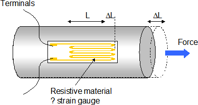
Figure 1 - a metal foil strain gauge
In this session we will investigate the use of strain gauges to measure the static properties of cantilever beams, and to build a weighing machine using this setup. A cantilever is a beam that is fixed at one end and free to move at the other as shown in Figure 2. We come across cantilevers in everyday life - sometimes in obvious ways - such as balconies on buildings and diving boards in swimming pools - sometimes in not so obvious ways - such as accelerometers in car air bag deployment systems, or the propeller blades of a helicopter.
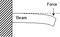
Figure 2 – cantilever beam
Cantilever beam
A simple but useful application of cantilever beams is as a weighing machine. In this experiment you will measure the static properties of a cantilever beam and then go on to build your own electronic scales.
In your experimental kit you should find
an aluminium cantilever beam with four strain gauges attached
an electronics kit (for building your amplifier)
a power supply
a selection of weights
a digital multimeter
a metre rule
a G-clamp
a commercial load cell
First of all you need to clamp the aluminium cantilever beam to the bench using the G-clamp - aligning the black line on the cantilever with the edge of the bench and having the longer part of the beam sticking out from the bench edge.
Next you need to switch on the power supply, press the '+20V meter display' then adjust the 20V supply knob until the output voltage shown on the display shows zero volts (turn the 20V supply knob fully counter-clockwise).
Next you need to connect the four leads from the strain gauges on the cantilever to the amplifier, the amplifier to the power supply and the 1k resistor to the amplifier (this resistor sets the gain of the amplifier to ~200) as shown in Figure 3.
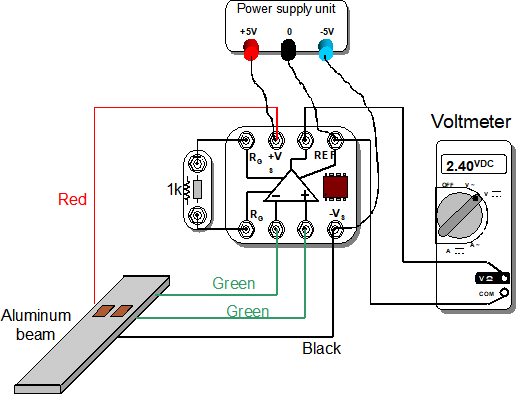
Figure 3 - connections for the cantilever experiment
Bridge circuit
When everything is connected as shown in Figure 3, connect a multimeter between the amplifier’s output terminal and its reference terminal - it should read close to zero volts, but don't worry if it does not as there could be some offset voltage in the amplifier or some degree of bending in the beam.
Now slowly turn the 20V power supply dial clockwise until the output voltage shown on the power supply’s display reads 5V. The amplifier is now ‘powered’ by a supply of +5V and -5V. The bridge formed by the four strain gauges will also have 10V across it (since it is also connected to the +5V and – 5V supply).
DO NOT INCREASE THE VOLTAGE SUPPLY BEYOND 5V SINCE THIS MIGHT DAMAGE THE STRAIN GAUGES.
The strain gauges are connected in a bridge arrangement as that shown in Figure 4: two strain gauges measure tension, and two strain gauges measure compression. This arrangement gives the best sensitivity and provides compensation for changes in resistance due to temperature.
When no load is applied on the cantilever all the strain gauges have the same resistance (~ 120W). The bridge is called 'balanced' in this case and the voltages at the two output terminals are equal giving a zero voltage difference at the output of the difference amplifier.
When a force is applied and the cantilever is deflected, then the resistance of the strain gauges will change producing different voltages at each of the output terminals of the bridge. The voltage difference in this case is greater than zero and proportional to the strain in the beam, i.e.
As you can see from this formula for the voltage that the signal is directly proportional to strain (and we removed the effect of the static resistance).
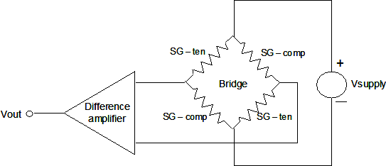
Figure 4 - Strain gauge bridge arrangement
Cantilever static response
We are now in a position to make some measurements. We will look at the static response of the cantilever. This will tell us how the applied force is related to the deflection of the beam.
Check the reading on your multimeter – it should still be near zero volts, but probably with a DC offset of a few tenths of a volt (this is due to residual strain in the cantilever and offset voltages in the amplifier circuitry – we could easily remove this DC offset with a simple additional circuit if so desired). Push gently on the free end of the cantilever – you should see the reading on the multimeter increase (or decrease) significantly. If this is not the case, ask for help, otherwise continue as described below.
For small deflections, the cantilever behaves in the same way as a simple spring. In other words, a force F applied to the end of the cantilever leads to a displacement x of the cantilever end given by the simple equation:
F = kx
where k is called the spring constant of the cantilever and has units of Newtons/metre.
Since the cantilever behaves in a similar fashion to a simple spring, with the displacement of the end of the cantilever being linearly related to the force applied (with the constant of proportionality being the spring constant k), then it is easy to see that the cantilever can be used to make a weighing machine - assuming the displacement x is proportional to the strain measured by the strain gauges, which for reasonable deflections is the case.
We will do a quick check to see how well the cantilever works as a weighing machine. Place a 100g weight on the end of the cantilever and write down the change in voltage seen on the multimeter and measure the corresponding deflection in the beam using the metre rule. Do the same with a 500g weight.
voltage at zero weight = ...................................... V
change in voltage for 100g weight = ...................................... V
beam deflection for 100g weight = ................................... cm
change in voltage for 500g weight = ..................................... V
beam deflection for 500g weight = ................................... cm
Is the cantilever linear over this range (i.e. is the voltage change for 500g five times that for 100g) ?
………………………………………………………………………………………………………………..
What is the spring constant, k, for the Aluminium beam?
………………………………………….. N/m
You can see from this simple experiment that the use of strain gauges in a bridge arrangement provides a proportional relationship between voltage and weight. Thus it would be possible for us to make a weighing machine if we can determine this proportional dependence. This is what we will do next, but we will use cantilever-like commercial ‘load-cell’ to make a more accurate weighing machine.
Building a weighing machine
The commercial load-cell measures the force exerted on a cantilever-like beam using an arrangement of 4 strain gauges (see Figure 5), just as in our home-made beams. As before, the gauges are connected in a bridge arrangement and we will use the output voltage from the bridge to measure weight.
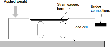
Figure 5 – Load cell
So, wire up the new circuit shown in Figure 6, and connect the digital multimeter across the output of the amplifier. Set the digital multimeter to measure DC voltage (V![]() ). Apply different weights on the free end of the load cell as indicated in Figure 5, and measure and record the output voltage from the amplifier on the graph given below. Start with the largest weight to scale your voltage axis on the graph correctly.
). Apply different weights on the free end of the load cell as indicated in Figure 5, and measure and record the output voltage from the amplifier on the graph given below. Start with the largest weight to scale your voltage axis on the graph correctly.
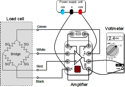
Figure 6 - Load cell connections
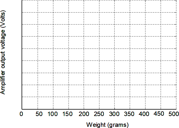
From the above graph, what would be the output voltage when a 375g weight is applied?
In a real weighing machine, such as the electronic scales you may have in your bathroom or the electronic scales used to weigh your shopping, the analogue voltage you have measured would be converted to digital form, calibrated and then shown as an actual weight on a digital display.
Counting coins contest!
Weighing machines are also useful for counting the number of small objects in a collection. A typical example is the coin counting machine that you find in a bank or outside a supermarket. Knowing the overall weight of the collection of coins and the weight of a single coin, these machines are able to tell you the number of coins in the collection.
You are given a jar that contains a number of 1p coins. The weight of the empty jar – including the cap – is 91.98g, and the weight of an individual 1p coin is 3.47g.
Using the weighing machine that you constructed from the load cell, your task is to find out the total number of 1p coins without counting them!
Estimated number of 1p coins = ..........................................
The group with the closest estimate of the number of coins to the actual value will win.
2025-06-21