EMS704 Simulation Approach for Articulated Robots using Agent-Based Modelling (ABM)
Hello, dear friend, you can consult us at any time if you have any questions, add WeChat: daixieit
Simulation Approach for Articulated Robots using Agent-Based Modelling (ABM)
Introduction to Agent-Based Modelling (ABM)
Agent-Based Modelling (ABM) is a simulation paradigm that models a system as a collection of autonomous, interacting agents, each following defined rules and behaviours. In the context of articulated robots, ABM is particularly powerful as it allows for decentralised control, where each joint or link can be modelled as an independent agent with its own decision-making process. This approach is highly suitable for capturing complex interactions, dependencies, and adaptive behaviours within robotic systems. ABM enables articulated robots to be modelled as multi-agent systems where each joint behaves autonomously but is influenced by interactions with other joints and the environment. This flexibility makes ABM ideal for simulating dynamic movements, adaptive control, and collaborative robotic tasks.
Decision to use ABM for Articulated Robots:
ABM is the best fit for simulating articulated robots for the following reasons:
1. Captures Complexity: Each joint can be treated as an agent with its own state variables (e.g., position, velocity, torque) and rules (For example, movement constraints, collision avoidance).
2. Handles Interactions: ABM effectively models joint-to-joint dependencies, torque effects, and external forces such as gravity and friction.
3. Scalability: The approach is scalable for multi-robot systems or swarm robotics, enabling collaborative tasks and coordinated movements.
4. Adaptability: ABM can incorporate learning algorithms such as Reinforcement
Learning, allowing joints to adapt to dynamic environments and optimise movements for efficiency and precision.
Assumptions & Limitations Of ABM:
While ABM is powerful, it comes with certain trade-offs such as:
• Computational Complexity: Higher processing power is needed as the number of agents (joints) increases.
• Detailed Behaviour Definitions Required: Each agent requires well-defined rules and decision-making processes.
• Complex Debugging: Interaction-heavy models may lead to unexpected emergent behaviours, making debugging more challenging.
Trade-offs Of ABM Compared to Other Approaches:
|
Approach |
Pros |
Cons |
|
ABM |
Handles individual joint behaviours, interactions, and adaptability |
Computationally expensive, requires detailed rule definitions |
|
Discrete-Event Simulation (DES) |
Efficient for task-based simulations |
Less suited for dynamic, adaptive robot control |
|
Monte Carlo Simulation (MCS) |
Good for uncertainty modelling |
Not designed for direct robot behaviour modelling |
|
Hybrid (ABM + MCS) |
Can simulate adaptive behaviours under uncertainty |
Even more computationally expensive |
ABM Implementation Plan:
1. Defining the Agents:
• Agents: Each joint of the articulated robot is an agent.
• State Variables: Position, velocity, acceleration, torque, and energy consumption.
• Behavioural Rules: Movement constraints (joint limits, singularities
avoidance), Interaction with adjacent joints (e.g., parent-child relationships), Collision avoidance and environmental constraints.
• Objectives: Achieve target positions, optimise movement efficiency, and adapt to dynamic obstacles.
2. Tools for Implementation
• MATLAB (Simulink and Simscape multi-body): We have decided to use
MATLAB as it is Powerful for engineering simulations with integrated tools for robotics.
• Tools to Use: We will use Simulink for block diagram modelling of joint interactions and control systems. Simscape multi-body for physics-based simulations of articulated robots.
3. Implementation Steps:
Model each joint as an independent block in Simulink.
Define joint dynamics and constraints using Simscape Multi-body.
Implement control logic and agent behaviours in Simulink.
Simulate and visualise articulated movements and interactions.
Diagram Showing Concept of Implementation:
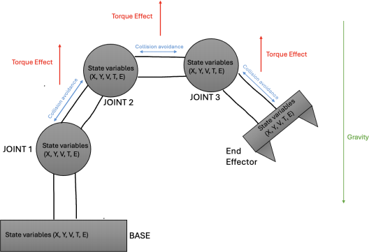
Table: State Variables and Descriptions:
|
State Variable |
Description |
|
X, Y |
Position in space (coordinates) |
|
V |
Velocity (speed and direction of movement) |
|
T (Torque) |
Rotational force applied to the joint |
|
E (Energy) |
Power consumption during movement |
Diagram Explanation:
This diagram represents an articulated robot modelled as a multi-agent system using Agent- Based Modelling. Each joint of the robot is treated as an independent agent, allowing for decentralised control and adaptive movement.
Key Components and Interactions:
1. Nodes as Agents:
• Each circle represents a joint of the articulated robot: Joint 1, Joint 2, Joint 3, and End Effector.
• The Base is where the robot is fixed to the ground.
• Each node (joint) operates as an independent agent, with its own state variables and behaviours.
2. State Variables Inside Each Node:
Each joint is labelled with (X, Y, V, T, E), representing its state variables:
• X, Y – Position in space (coordinates).
• V – Velocity (speed and direction).
• T (Torque) – Rotational force applied to the joint.
• E (Energy) – Power consumption during movement.
These variables allow each joint to interact with its environment and adjacent joints.
3. Torque Effect (Red Arrows): Red arrows are placed between each pair of joints, pointing upward. They indicate the Torque Effect, showing that rotation or force in one joint influences the next. This effect flows upward from Joint 1 to the End Effector, illustrating the cascading influence of torque along the robotic arm.
4. Collision Avoidance (Blue Arrows): Blue arrows between joints show Collision Avoidance rules. They are bidirectional, indicating that each joint is aware of its neighbours, preventing them from colliding or overlapping. This ensures smooth and safe movement of the articulated arm.
5. Gravity (Green Arrow): A green arrow is placed on the right side of the robotic arm, pointing downwards. It shows that gravity affects the entire robot, influencing all joints equally. This simplifies the diagram while accurately representing the environmental force acting on the robot.
6. Base as a Fixed Agent: The Base is shown at the bottom, with no Torque Effect arrows leading to it. This represents the fact that the base is fixed to the ground and acts as the anchor point for the robotic arm.
7. End Effector as the Goal Node: The End Effector is the final node, representing the tool or hand of the robotic arm. It inherits the cumulative effects from all preceding joints, influencing its final position and movement.
Conclusion
Agent-Based Modelling (ABM) is a suitable and robust approach for simulating articulated robots due to its ability to capture complex interactions, adaptive behaviours, and decentralised control. The implementation can be efficiently achieved using MATLAB (with Simulink and Simscape Multi-body). ABM provides a scalable and flexible framework, making it ideal for modelling articulated robotic systems.
2025-06-19