Digital Design Assignment 1 Digital Combination Lock
Hello, dear friend, you can consult us at any time if you have any questions, add WeChat: daixieit
Digital Design
Assignment 1
Digital Combination Lock
1 Introduction
The aim of the assignment is to design a combination lock using VHDL and synchronous design techniques, and to implement your design on the FPGA board. The user interface will be simple and based on use of the push buttons, slider switches, LEDs and 7-segment display on the FPGA board.
Part 1 of this assignment (in section 2of this assignment sheet) is identical to lab 4.
1.2 Format of report and submission procedure
The assignment should be written up as a report (an appropriate length would be between 7 and 15 pages, not including any appendices) and submitted through Canvas by Monday 7th April. The report should be submitted as a pdf file using single line spacing for the main text. The report should contain the following sections:
Title page
Executive summary: This section should not exceed 150 words and should provide a brief overview and summary of the report
Introduction: This section should introduce the reader to the purpose of the assignment and can provide a brief summary of the relevant background.
Design: This section should provide a summary of the system that you implemented and an explanation of the key points involved in implementation. This should include diagrams of the system. You may, if you wish, include small blocks of code in the explanation if they illustrate some useful point about the design, but long blocks of code or long descriptions of the features of the VHDL language would not be appropriate in the main text of the report.
Results: This section should contain simulations that demonstrate the correct operation of the design. The explanations accompanying the simulations should explain the key features of the waveforms and the conclusion that can be drawn from the simulation results. The report should make clear how it was established that the results are correct. It should also contain a summary of the synthesis results (including information about how much hardware is used by your design, whether your design could have fitted into a smaller device than the Artix 7 FPGA on the board, and your opinions about which parts of your design consume the most hardware).
Evaluation and conclusions: This section should explain the strengths and weaknesses of your final design, and should explain any ideas you have for how the design could be improved.
1.3 Additional materials to submit
The report should be accompanied by a video of approximately 3 minutes length, which explains your main results and how a user would interact with your design.
You should also submit an electronic copy of your Vivado project, including the VHDL and XDC files, through Canvas.
1.4 Mark scheme
Video demonstration 15%
Style, structure and presentation of report 15%
Description of system analysis and design process 15%
Technical achievements in design, implementation and evaluation 45%
Demonstration of originality and creativity 10%
Technical achievement in design is based on the number and quality of the features that you successfully implemented. Technical achievement in implementation is based on the quality of your VHDL code. This includes issues such as legibility of code, use of meaningful variable names, good comments, clear structure, and modifiability of the design. Technical achievement in evaluation is based on the quality of your simulation and synthesis results, how well they have been planned and interpreted.
Originality entails thinking of additional features that can be incorporated into the design that are useful to the user.
An excellent submission might have the following characteristics: The report was clear and logically presented with a good explanation of the strengths and limitations of the design. The simulation results were explained and annotated well to provide a clear illustration of how the design worked. The final results were verified as correct. The code had good comments, clear layout, good coding style, and meaningful signal and entity names. Some useful additional features were implemented that go beyond the basic features in the assignment sheet and provide a useful enhancement to the functionality.
A Failing submission might have the following characteristics: The report had a few diagrams and code listings with no linking explanations. The simulation results were uninformative because the intermediate values and final values could not be read. No explanation was given as to how the student had attempted to verify the functionality. The code was difficult to decipher; it was incomplete and some sections would not compile.
English language
A report must meet the following standards to pass:
The work is written to an acceptable standard of English
Spelling, punctuation, vocabulary, sentence construction, and textual coherence is of an acceptable standard.
A report that does not reach the above standard or falls into the categories below will fail:
Poor standard of written English, making it difficult to understand the points being made.
Weaknesses of writing are so frequent or serious that they impede communication.
1.5 Generative AI
None of the final text of the report or the final code should have been produced by generative AI.
Use of generative AI to generate materials for background research and self-study is permitted.
2 A simple digital combination lock
The code sequence that you will be required to implement is the last six digits of your student ID number. So, for example, if your ID is 1299562, then your code sequence will be the digits 2,9,9,5,6,2.
The user interface will operate as follows:
One of the push buttons will be used to indicate that the user wishes to enter a code sequence.
A digit will be entered as a binary number on the slider switches
Once the digit has been a set up on the slider switches, a second button will be used by the user to indicate that the first digit is ready to be read.
The user then uses the slider switches and the second push button to enter the remaining three digits.
If the code sequence is correct, then some suitable visual indication will be given (for example, you might choose to light up all the LEDs).
3 Improving the user interface
As the user enters the four digits, they should be displayed on the 8-digit 7-segment display.
After the six digits have been entered, if the code entered is incorrect, the display should indicate to the user that the lock will not open by setting the display to read:
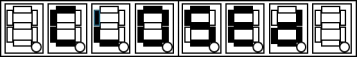
The display of “Closed” should alternate at one second intervals with display of the number entered.
If the code entered is correct, the display should indicate to the user that the code is OK by setting the display to read:
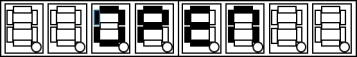
The display of “Open” should alternate at one second intervals with display of the number entered.
Satisfactory completion of the basic lock with this interface will be sufficient for a pass mark.
4 A more advanced solution
We are all accustomed to entering passwords to log in to a service on a computer. One problem with passwords is that someone could look over your shoulder and see what password you are typing. Alternatively, spy software that logs your keyboard activity could be installed secretly onto your computer to intercept your password. Highly secure systems (like online banking systems) try to deal with this problem by never asking the user to enter the whole password in a single login. Instead, they will ask, for example, for the user to enter the 3rd, 4th and 6th letter in the password. Then the next time the user logs in, a different three letters will be requested.
Modify your combination lock design so that it will request the user to type in three of the digits in the code sequence. The system will prompt the user to show which three numbers should be entered. Each time the user attempts to gain access, the system will make a different choice of which of the numbers in the code sequence must be entered.
The user interface should operate as follows:
A third push button will be used to indicate that the user wishes to be prompted to enter two numbers from the code sequence.
The system will choose a random number in the range 0 to 5 and display it to the user. The user enters the corresponding number from the code sequence using the slider switches and the second push button as normal.
The system will then choose a different random number in the range 0 to 5 and display it to the user. The user enters the corresponding number from the code sequence.
The system will then choose a different random number in the range 0 to 5 and display it to the user. The user enters the corresponding number from the code sequence.
If the three digits are correct, then the system unlocks
There are several possible ways to make a random number generator, but the simplest is to use a very high speed counter that starts counting at the full clock rate of the FPGA as soon as the system is powered up. When the user presses the third push button the counter stops counting. The low order bits of the counter can be regarded as a random number.
2025-04-17