SE 310 Fall 2021 Project II
Hello, dear friend, you can consult us at any time if you have any questions, add WeChat: daixieit
SE 310 Fall 2021
Project II
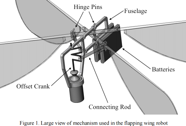
There has been a growing interest in flapping wing robots over the last decade, which are based on the flapping hovering flight of insects and birds. A number of hovering flapping robots have been successfully demonstrated by different research groups. One of these designs takes advantage of 3D printing for demonstrating a simple design of a flapping wing robot. This robot consists of two different inversions of a four-bar mechanism and wings other than a motor and lithium polymer batteries. Both the mechanism and wings are 3D printed. Figure 1 shows the design of this robot.
Design Objective
Design a crank rocker inversion of a four-bar mechanism. The mechanism is used for converting rotary motion from a motor to flapping motion of the wings. Using the Matlab/Python code provided for the project is highly recommended.
You have to come up with a design that permits compact operation (i.e. O2E in Fig. 2 must not rotate more than 60 degrees) and also ensure that the maximum velocity of the wing tip (E in Fig. 2) at least 6000 mm/second. Schematic of the four-bar mechanism, its link lengths and other variables are shown in Fig. 2. Length of the crank is ‘a’ and it should make a complete rotation about its fixed end, O1 . Length of wing is ‘e’ (O2E = e) and it is pivoted at O2 . Note that O2 must lie right above O1 as in Fig. 2
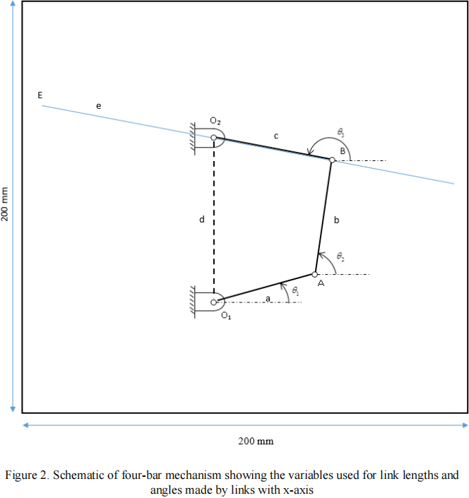
The Matlab/Python code plots the path traced by the wing tip, E, to enable you to visualize the
range of its motion. The code outputs the angle by which the wing rotates during each flapping motion i.e., the angle subtended by O2E at O2 . The code also outputs the maximum tip velocity of point E.
Design Variables:
1. Link lengths of the mechanism (a, b, c & d)
2. Length of the wings (e)
Design Parameters and Constraints:
1. Crank ofthe four-bar mechanism should make a complete rotation. Crank is connected to the output shaft ofthe motor, so it has to make a complete rotation.
2. Four-bar mechanism and the wings should fit within a 200 mm x 200 mm footprint throughout its range of motion. The figure output of the Matlab program has its axis going from - 100 to 100. Four-bar and wings should fit completely within this figure window.
3. Maximum wingspan (e) ofthe robot can be up to 100 mm.
4. The length ofthe crank O1A must be more than 10 mm.
5. Motor is assumed to have a constant angular velocity of 900 rpm. This value is taken as the angular velocity ofthe crank.
6. Wings should rotate more than 450 and not more than 60o about its pivot, O2 .
Questions:
I. Design two feasible mechanisms that meets the above constraints. For the first design,
a. First enter the link lengths in the MATLAB/Python program. Ensure that the crank rotates 3600 by applying the Grashoff’s criterion. The MATLAB/Python code will give you an error if the criterion is not satisfied.
b. The code outputs a value called ‘range’ which is the range of wing rotation about the pivot, O2 .
c. The code also gives the maximum tip velocity as ‘tip_vel’
II. Reconfigure the link lengths such that the tip velocity increases (from your first design) while meeting all other constraints (2-7)
2021-12-08