EEL-5813 Neural Networks
Hello, dear friend, you can consult us at any time if you have any questions, add WeChat: daixieit
EEL-5813 Neural Networks FALL 2021
INDIVIDUAL PROJECT II Multi-Layer Perceptron (MLP) with Backpropagation(BP)
OBJECTIVE: In this project the student will apply the basic “Backpropagation of Errors” (Backpropagation, Backprop or BP) to the training of a feedforward neural network with an input layer and TWO layers with adaptable weights and biases: A HIDDEN LAYER and an output layer. That is, the project will implement a “Multi-Layer Perceptron” (MLP).
The network will be trained to classify column vectors containing 25 “+1” or “-1” values that represent pixels turned “ON” or “OFF”, respectively, in 5 x 5 arrays, such as the ones depicted in Figure P2-1.
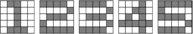 |
Figure P2-1 “Ideal” or “perfect” 5 x 5 arrays representing digits 1, 2, 3, 4, and 5.
The numerical vectors PROVIDED to the students in the 25 x 250 matrix PPRJ2 represent 250 “imperfect” digits (50 of each digit) where 1 or 2 pixels have been “toggled” (toggled = if the pixel was +1 it will now be -1, and vice versa) at random. Each column in matrix PPRJ2 contains the values of the pixels after the 5x5 array has been “scanned by columns” (left to right, and top
to bottom within each column). For example, if the kth column of matrix PPRJ2 represented the “perfect” 2 shown above, it would be (shown transposed, “ ’ “):
PPRJ2(:,k)’ = [ 1 -1 -1 1 1 1 -1 1 -1 1 1 -1 1 -1 1 1 -1 1 -1 1 -1 1 -1 -1 1 ]
The known identity of each one of the 250 columns of matrix PPRJ2 is specified in the 1 x 250 row vector TPRJ2, with a digit that can be 1, 2, 3, 4, or 5, depending of the digit represented by the corresponding column of PPRJ2. For example, the kth entry in TPRJ2 would have a value of “2”.
TPRJ2(1,k) = 2
The student will use the same type of neural network architecture to implement (SEPARATELY) a “1-detector” , a “2-detector”, a “3-detector”, a “4-detector” and a “5- detector”. In each case the architecture will have 25 input processing elements (PE s) in the input layer, H PE s in the “hidden layer” and ONLY 1 PE in the output layer, which should turn “ON” (output activation = +1) ONLY WHEN A PATTERN OF THE TYPE SOUGHT IS
PRESENTED TO THE INPUT LAYER, and “OFF” (output activation = -1) WHEN A PATTERN OF A DIFFERENT TYPE IS PRESENTED.
To obtain a vector with only +1 and -1 entries that can be used as “targets” for the classification of a SPECIFIC DIGIT from the TPRJ2 vector PROVIDED to the students, the following
sequence of instructions can be used (This example is to CREATE A TARGET VECTOR, T4SS, FOR the “4 classifier”):
T4SS = ones(size(TPRJ2)) * (-1); indxs = find(TPRJ2 ==4); T4SS(indxs) = 1;
Students will need to create 5 target vectors: T1SS, T2SS, T3SS, T4SS and T5SS. All of them will be 1 x 250 row vectors.
DATA PREPARATION: Separating VALIDATION [TT] and TEST [TS] sets (“splits”)
To monitor the progress of the training process, where the weights and biases in the network are changed using the TRAINING [TR] SET, students will need to PARTITION the patterns and targets received by them in 3 SUB-SETS. Students are REQUIRED TO KEEP 175 patterns (i. e., 70%) for actual training, that is, the TRAINING [TR] SET. Then students can decide how many of the remaining patterns should be used for VALIDATION [TT] and how many to keep for “final testing” [TS]. If, for example, 40 patterns are kept for validation and 35 for “final testing”, the partition could be performed like this:
% Separate TRAINING SET (inputs and targets): TRP = PPRJ2(:,1:175);
TR1 = T1SS(1,1:175); TR2 = T2SS(1,1:175); TR3 = T3SS(1,1:175); TR4 = T4SS(1,1:175); TR5 = T5SS(1,1:175);
% Separate VALIDATION (TT) SET (inputs and targets): TTP = PPRJ2(:,176:215);
TT1 = T1SS(:,176:215); TT2 = T2SS(:,176:215); TT3 = T3SS(:,176:215); TT4 = T4SS(:,176:215); TT5 = T5SS(:,176:215);
% Separate FINAL TESTING (TS) SET (inputs and targets): TSP = PPRJ2(:,216:250);
TS1 = T1SS(:,216:250); TS2 = T2SS(:,216:250); TS3 = T3SS(:,216:250); TS4 = T4SS(:,216:250); TS5 = T5SS(:,216:250);
PART I : “1-detector”
The network for “detecting digit 1” will have 25 input PE s, H PE s in the hidden layer and ONE output PE.
The basic BP approach will use only one learning rate “a”, which will be assigned before the start of the training run and will be kept constant throughout the training run.
For BP the basic initialization guidance is to initialize all the weights and biases with “small random values”. For standardization, here students MUST INITIALIZE ALL THE WEIGHTS TO “0”, AND ALL THE BIASES TO “0.5”.
The initial learning runs will go on until MAXEPOCHS (to be decided by the student) have been completed, BUT every 10 epochs of effective training with the [TR] set, the current weights and biases should be used to process the [TT] set, recording the MSE achieved. Then the effective training with [TR] may continue.
After completion of the training run a PLOT (let’s call it “Training & Validation MSE Plot”) where all the MSE values obtained after each epoch with the [TR] set, and the MSE values obtained from the [TT] set every 10 epochs should be displayed. – BASED ON THE APPEARANCE OF THIS PLOT, the student will determine the number of epochs, TERMEPOCHS, when a SECOND (and final) training run (using the same a and H) should be terminated, to yield the “final trained weights and biases”.
For the “1-detector”, the student must try different combinations of the following HYPERPARAMETERS:
- a (Constant Learning Rate)
- H (Number of Processing Elements in the “Hidden Layer”)
While the student can experiment with as many combinations of these hyperparameters as necessary, the student MUST PRESENT AT LEAST 4 “Training & Validation MSE Plots” and they must include experimentation with at least 2 values of a and at least 2 values of H. (Make sure to indicate the values of a, H and MAXEPOCH used for each plot shown.)
Then, the student will choose one (“the best”) of the 4 (or more) “Training & Validation MSE Plots” shown and will use the same a and H to run one final training run but now the training will be stopped after TERMEPOCHS to yield the “final trained weights and biases” for the “1- detector” (TERMEPOCHS ≤ MAXEPOCHS from the plot selected). THIS FIFTH PLOT (stopping at TERMEPOCHS), must also be included in the report, specifying the a and H used and the value of TERMEPOCHS.
Finally, the student must test and indicate if the results from the network with the “final trained weights and biases” classify the patterns in the “Final Testing Set” [TS] correctly (“hit”) or “incorrectly” (miss). Then the student must calculate and indicate in the report the “Hit Ratio”.
PART II : “2-detector”
The student will proceed IN THE SAME WAY AS FOR PART I (“1-Detector”). The key difference is that, this time the TARGET VECTORS will not be TR1 (for training, changing the weights), TT1 (for validation, which Does NOT change the weights) and TS1 for “final testing”, but instead TR2, TT2 and TS2, respectively.
The “best” values of H, a and TERMEPOCHS for this detector must be defined independently, on the bases of the results seen by the students FOR THIS PART. (It would be OK if they are the same as for previous parts, but they can also be different).
PART III : “3-detector”
The student will proceed IN THE SAME WAY AS FOR PART I (“1-Detector”). The key difference is that, this time the TARGET VECTORS will not be TR1 (for training, changing the weights), TT1 (for validation, which Does NOT change the weights) and TS1 for “final testing”, but instead TR3, TT3 and TS3, respectively.
The “best” values of H, a and TERMEPOCHS for this detector must be defined independently, on the bases of the results seen by the students FOR THIS PART. (It would be OK if they are the same as for previous parts, but they can also be different).
PART IV : “4-detector”
The student will proceed IN THE SAME WAY AS FOR PART I (“1-Detector”). The key difference is that, this time the TARGET VECTORS will not be TR1 (for training, changing the weights), TT1 (for validation, which Does NOT change the weights) and TS1 for “final testing”, but instead TR4, TT4 and TS4, respectively.
The “best” values of H, a and TERMEPOCHS for this detector must be defined independently, on the bases of the results seen by the students FOR THIS PART. (It would be OK if they are the same as for previous parts, but they can also be different).
PART V : “5-detector”
The student will proceed IN THE SAME WAY AS FOR PART I (“1-Detector”). The key difference is that, this time the TARGET VECTORS will not be TR1 (for training, changing the weights), TT1 (for validation, which Does NOT change the weights) and TS1 for “final testing”, but instead TR5, TT5 and TS5, respectively.
The “best” values of H, a and TERMEPOCHS for this detector must be defined independently, on the bases of the results seen by the students FOR THIS PART. (It would be OK if they are the same as for previous parts, but they can also be different).
PART VI – Observations and Conclusions
The student must write a brief final section indicating the observations s/he made and comparing the processes carried out for parts I – V. This brief section must also contain conclusions from the student.
IMPORTANT NOTES:
[1] The report MUST ALSO INCLUDE a brief INTRODUCTION, explaining the project (at the beginning of the report).
[2] After PART VI, the report MUST INCLUDE an APPENDIX with the listings of all the code used for the development of the project.
[3] The printed, self-contained, report must be submitted in physical (printed) form during the lecture time, on the assigned due date.
2021-11-29