CS211 Programming Assignment IV
Hello, dear friend, you can consult us at any time if you have any questions, add WeChat: daixieit
CS211 Fall 2021
Programming Assignment IV
This assignment will provide more practice programming in C and working with circuits and digital logic. You will write a program that reads a circuit specification and generates a truth table for that circuit. Section 2 describes the required interface and behavior of your program, and section 3 describes the specification language.
Advice Start working early. Before you do any coding, make sure you can run the auto-grader, create a Tar archive, and submit that archive to Canvas. You don’t want to discover on the last day that scp doesn’t work on your personal machine.
Decide your data structures and algorithms first. Section 4 describes one method for implementing the program that performs well, but you are free to design your own. Writing out pseudocode is not required, but it may be a good idea.
When writing your program, use the auto-grader to create the build directory, and use make in that directory to compile your code. This will save you time, keep your source code separated from your compiled files, and ensure that you are compiling your program consistently.
Start working early. You will almost certainly encounter problems you did not anticipate while writing this project. It’s much better if you find them in the first week.
1 Overview
You will write a program truthtable that reads a file containing a description of a circuit, and prints that circuit’s truth table. The files specify (1) the number and names of each input to the circuit, (2) the number and names of each output from the circuit, and (3) the logic gates and components that make up the circuit. In order to indicate the connections between gates, each connection is also given a name.
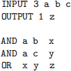
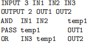
For example, this is a description for a circuit that implements a 3-argument AND gate:
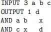
Note that it contains three inputs (a, b, and c), a single output (d), and two AND gates, each of which has two inputs and one output. The variable x indicates an internal connection between the first AND gate and the second. See section 3 for details on the specification language.
When given this file, truthtable should print:
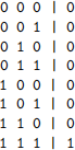
The three columns on the left correspond to the three inputs, and the column to the right corresponds to the output.
This assignment has two parts:
Part 1 (100 points) For this part, the circuit descriptions will be sorted so that each temporary variable appears as an output parameter before any appearances as an input variable.
Part 2 (Extra Credit) For this part, the circuit descriptions will not be sorted, meaning that a temporary variable may be used as an input parameter before its use as an output parameter.
2 Program
truthtable takes a single argument, which is the name of a file containing a circuit description. The behavior of truthtable is unspecified if it receives no arguments or more than one argument, but you should still check that the number of arguments is correct. (One possibility is to have truthtable read from standard input if no file argument is given.)
Usage
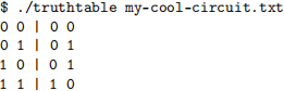
Input The input to your program will be a single circuit description using the language described in section 3. The first argument to truthtable will identify a file containing this circuit description.
You MAY assume that the input is correctly formatted and that no variable depends on its own output.
Output The output of truthtable is a truth table showing each combination of inputs and the corresponding output for the specified circuit. Each column in the table corresponds to a specific input or output variable, which are given in the same order as their declaration in the INPUT and OUTPUT directives. Columns are separated by a single space, and a vertical bar (|) occurs between the input and output variables.
Note that no white space follows the final column.
3 Specification Language
In this language, circuits are specified with a series of directives. These directives refer to various named variables, which correspond to wires in a circuit diagram. Many of the directives describe a logic gate or similar building block, indicating which varibles correspond to its input and output.
Each directive has the form of a name followed by one or more parameters, separated by whitespace. The name indicates which directive and determines the number of parameters. Some directives take a variable number of parameters; their first parameter will always be an integer which is used to determine the number of parameters. Depending on the directive, some parameters will be inputs and some will be outputs.
Variables in a circuit can be classified into three non-overlapping sets. Input variables must be declared by the INPUT directive, and may only occur as input parameters. Output variables must be declared by the OUTPUT directive and may occur exactly once in an output parameter. All other variables are temporary variables and must occur exactly once as an output parameter and zero or more times as an input parameter.
A variable name consists of a letter followed by zero or more letters or digits. You may assume that variable names are no longer than 16 characters.
In addition to variables, the constant inputs 0 and 1 may be used as input parameters. These are always false and always true, respectively.
Finally, _ may be used as the output of a gate, indicating that the output of a gate is discarded. Use of _ is equivalent to using a temporary variable that is not used as an input to any other gate.
Note that whitespace may include one or more spaces, tabs, or newline characters. It is recommended to use fscanf() to read the files, and to use a format code such as " %16s" to skip whitespace before reading the next variable or directive name.
By convention, we will use multiple spaces to separate the inputs and outputs of a gate, but this is not required and has no special meaning. It is purely for readability. Similarly, we will often put a blank line between OUTPUT and the first gate, but this is also done purely for readability. Your program should treat repeated newlines the same as single newlines (or, ideally, the same as any whitespace).
Use of fgets() is not recommended and will only make your life harder. Remember that fscanf() is not limited to reading an entire line at once.
3.1 Directives
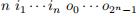
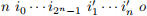
This section describes each of the directives used to describe a circuit. Each directive is followed by several parameters. A parameter n is always an integer and has a special meaning. Input parameters are indicated as i and output parameters are indicated as o. Ellipses (· · ·) are used to indicate a variable number of parameters.
● INPUT

Declares n input variables. This directive must always occur first in a circuit description.
● OUTPUT

Declares n output variables. This directive must always occur second in a circuit description.
● NOT

Represents a not gate in logic design. Computes

● AND

Represents an and gate in logic design. Computes

● OR
Represents an or gate in logic design. Computes

● NAND
Represents a nand gate in logic design. Computes

● NOR
Represents a nor gate in logic design. Computes

● XOR
Represents an xor gate in logic design. Computes
where ⊕ indicates exclusive or.
● DECODER
Represents an
decoder gate in logic design. The first argument gives the number of inputs, n. The next n parameters are the inputs, followed by
parameters indicating the outputs.
The inputs are interpreted as an n-bit binary number s in the range 0, · · · ,
is the least significant bit. The output
will be 1 and all others will be 0.
● MULTIPLEXER
Represents a
, respectively. The first parameter, n, gives the number of selectors. The next
The selector inputs are interpreted as an n-bit binary number s in the range 0, · · · ,
The output is

● PASS

Represents the absence of a gate. Computes o = i. This may be used to convert a temporary variable into an output variable.
3.2 Parsing
The specification language can be thought of as a sequence of tokens separated by whitespace. No keyword or variable name in the language exceeds 16 characters, so it is safe to use fscanf() with the format code %16s, which will read a token of up to 16 non-whitespace characters.
Each directive will be either be followed by a fixed number of parameters or by a number that will determine the number of parameters. Thus, your parsing code will always be able to tell whether it expects a directive name, integer, input parameter, or output parameter next.
For safety, your program should always check that fscanf() succeeded and that it received the expected token type. If something has gone wrong, either because of bad input or a program error, you want to know about it!
3.3 Examples
This circuit describes a half-adder, where s is the sum and c is the carry.

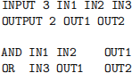
This circuit computes z = ab + ac:
Note that x and y are temporary variables, since they were not declared in INPUT or OUTPUT.
This circuit description is invalid, becuase it uses an output variable as an input parameter:
This can be rewritten using PASS:
This circuit demonstrates the user of MULTIPLEXER:
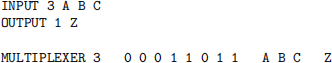
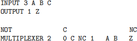
As shown in class, this can be re-written to use a 4:1 multiplexer:
An equivalent circuit can be made using a 3:8 decoder:
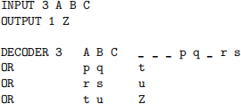
Note the use of _ for discarded outputs from the decoder.
4 Implementation suggestions
There are many ways to design truthtable, but the most efficient way is to create a data structure that represents a circuit. Your program will read the circuit description file, create the corresponding data structure, and then use that structure to determine the output values for each combination of inputs.
Students commonly try to build the entire truth table before printing it. This is not the best strategy, because the truth tables grow exponentially with the number of inputs. (For example, test 1.10 will produce a truth table with  rows.) A better design is to generate and print the table one row at a time.
A few tips for creating fast implementations of truthtable.
● When reading the circuit description file, assign a number to each new variable name and use a linked list or other structure to maintain a table that you can use to look up the number assigned to previously seen variables. Internally, refer to variables by number rather than name: integer comparisons are faster than string comparisons, and you can use variable numbers as array indices.
● Carefully consider what information you need to represent a circuit. This will likely include the circuit’s input and outputs and the gates making up the circuit.
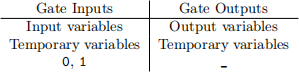
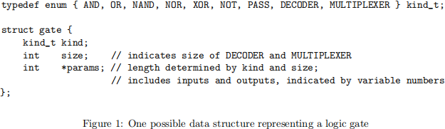
● Carefully consider what data is needed to represent a gate. Design a structure that is general enough to represent any gate, and then write code that can handle any of the gates. This will likely include a code that indicates the type of gate and the input and output variables. See fig. 1 for one possibility.
● In order to handle DECODER and MULTIPLEXER, your gates will need to work with a variable number of inputs and outputs. One possibility is to use an array of variable numbers representing the inputs and outputs along with a field indicating the size of the gate. For fixed-sized gates, such as AND, this number can simply be ignored and the array can be assumed to contain the correct number of inputs and outputs. For MULTIPLEXER and DECODER, one number is sufficient to determine how many inputs and outputs there are.
● To generate a single row of the truth table, first assign values to the circuit inputs. Then, for each gate, determine the values for its outputs based on the values of its inputs. Once every gate has been handled, you will know the values for the outputs and can print the table row.
If you have assigned a unique number to each variable, then you can use an array to hold the values of all the variables.
● For each row of the truth table, note that every input value will be followed by a space, and every output value will be preceded by a space.
● When reading the circuit description, you may assume that the file is correctly formatted. Thus, after reading a directive name, you may assume that it will be followed by the correct number of parameters. Thus, it is acceptable to use the whitespace-skipping tokenizer and ignore line breaks.
● When using a format string such as " %16s" with fscanf(), the corresponding variable must be the address of an array containing a sufficient number of characters (17, in this case). While it is fine to use local variable to hold the result from fscanf(), be sure to make a copy of the string if you intend to hold onto it.
● There are several methods for dealing with circuit descriptions where the gates are not given in order. One way is easy to write, but slow. Another is more complicated, but fast. (Hint: the circuit can be thought of as a directed, acyclic graph, and you have learned an algorithm for ordering the nodes in a DAG.)
5 Submission
Your solution to the assignment will be submitted through Canvas. You will submit a Tar archive file containing the source code and makefiles for your project. Your archive should not include any compiled code or object files.
Your submission MUST be properly formatted. You are responsible for ensuring that your submission can be tested with the auto-grader. You will not receive full credit for submissions that must be modified in order to be graded. You are strongly encouraged to test your archive before submitting, as described in section 5.4. If you are submitting from a different computer than you have used for testing, make sure that your archive was correctly transferred!
The remainder of this section describes the directory structure, the requirements for your makefiles, how to create the archive, how to use the provided auto-grader, and how to create your own test files to supplement the auto grader.
5.1 Quick start
These steps will unpack the auto-grader archive, set up your src directory and make file, and use the auto-grader to create the build directory. The auto-grader is flexible and many of these steps can be customized. See the remainder of this section for more in-depth explanations.
Unpacking the auto-grader archive will create a directory pa4 containing the auto-grader and associated test data. First, move to the directory you want to contain the pa4 directory and unpack the archive. You can move the archive to this directory first, or simply give a path to its location. E.g.,
Next, move into the pa4 directory and set up your src and build directories.
Write your code in a file src/truthtable.c using your editor of choice.
Compile in the build directory using make.
If you are repeatedly compiling and testing with a specific test file, you can combine both steps into a single command using &&.
This works well in combination with the up-arrow key (used to repeat earlier commands).
5.2 Directory structure
Your project should be stored in a directory named src, which will contain (1) a makefile, and (2) any source files needed to compile your program. Typically, you will provide a single C file named for the program (truthtable.c).
This diagram shows the layout of a typical project:
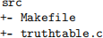
Note that your code and makefile go directly in src, without any subdirectories.
5.3 Makefiles
We will use make to manage compilation. Your src directory will contain a file named Makefile that describes at least two targets. The first target must compile the program. An additional target, clean, must delete any files created when compiling the program (typically just the compiled program).
For reference, this makefile is provided with the auto-grader in the file template.make:
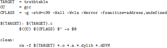
You may move this file to your source directory and rename it Makefile.
Note that the command for compiling truthtable uses warnings and includes AddressSanitizer and UBSan. Your score may be reduced if your makefile does not include these options.
Use of -g is recommended, but not required.
If you prefer to name your source code file something other than truthtable.c, simply replace $(TARGET).c with your preferred name. Use of multiple source files is permitted, but contact me for tips first.
You are free to design your own makefile, but be sure to use the variables $^ or $< to refer to your source files so that make can find your source files. Contact me if you have trouble getting your makefile to work.
Note that the makefile format requires that lines be indented using a single tab, not spaces. Be aware that copying and pasting text from this document will “helpfully” convert the indentation to spaces. You will need to replace them with tabs (literal tab characters), or simply type the makefile yourself. You are advised to use make when compiling your program, as this will ensure (1) that your makefile works, and (2) that you are testing your program with the same compiler options that the auto-grader will use.
5.4 Creating the archive
We will use tar to create the archive file. While in the directory containing src, execute this command:
tar will create a file pa4.tar that contains your makefile and source code. (If you are using multiple source files, or have re-named your source code, you will need to adjust this command accordingly.) This file can now be submitted through Canvas.
To verify that the archive contains the necessary files, you can print a list of the files contained in the archive with this command:
You should also use the auto-grader to confirm that your archive is correctly structured.
5.5 Using the auto-grader
We have provided a tool for checking the correctness of your project. The auto-grader will compile your programs and execute them several times with different arguments, comparing the results against the expected results.
Setup The auto-grader is distributed as an archive file pa4_grader.tar. To unpack the archive, move the archive to a directory and use this command:
This will create a directory pa4 containing the auto-grader itself, grader.py, a library autograde.py, abd a directory of test cases data.
Do not modify any of the files provided by the auto-grader. Doing so may prevent the auto-grader from correctly assessing your program.
Usage While in the same directory as grader.py and src, use this command:
The auto-grader will create a directory build, and compile your program using the make file and source code in src, placing compiler outputs in build.
During development, you may prefer to use the --stop or -1 option, which produces more program output but stops after the first failed test case.
The tests for this assignment come in two groups, for normal and extra credit. To test only a single part, include an argument truthtable:1 or truthtable:2.
To obtain usage information, use the -h option.
Program output By default, the auto-grader will not print the output from your programs, except for lines that are incorrect. To see all program output for all unsuccessful tests, use the --verbose or -v option:
To see program output for all tests, use -vv. To see no program output, use -q.
Checking your archive We recommend that you use the auto-grader to check an archive before submitting. To do this, use the --archive or -a option with the archive file name. For example,
This will unpack the archive into a temporary directory, grade the programs, and then delete the temporary directory.
Specifying source directory If your src directory is not located in the same directory as grader.py, you may specify it using the --src or -s option. For example,
2021-11-23