Project 1 CDA 4630/5636: Embedded Systems
Posted: February 1, 2020 Total: 10 points Due: February 12, 2020, 11:30 pm (EST)
This is an individual assignment. You are not allowed to take or give any help in completing this project.
Please strictly follow the submission instructions (outlined at the end of this document) and submit your source code in Canvas (http://elearning.ufl.edu/) before the deadline. Please include the following sentence on top of your submission: “I have neither given nor received any unauthorized aid on this assignment”.
Petri Net Simulator of a Simple Processor: In this project you will create a Petri Net simulator for a simplified ARM Processor. Please use C, C++ or Java to develop your simulator. The model will use colored tokens (token with values) rather than the default Petri net. Your simulator should be able to generate step-by-step simulation of the Petri net model of the processor described below. Please go through this document first and then view the sample input/output files in the class assignments page.
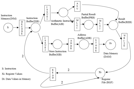
Figure 1. Petri Net Model of a Simple Processor
THREE IMPORTANT PLACES
1. Instruction Memory (INM):
The processor to be simulated only supports four types of instructions: Add (ADD), Subtract (SUB), Multiply (MUL) and Store (ST). At a time step, the place denoted as Instruction Memory (INM) can have up to 16 instruction tokens. This is shown as Ii in Figure 1. We will provide an input file (instructions.txt) with instruction tokens. It supports the following instruction format. Please note that the “First Source Operand” is always register. The “Second Source Operand” is register for arithmetic instructions (ADD, SUB and MUL) and immediate value for store (ST) instruction.
2. Register File (RGF):
3. Data Memory (DAM):
TEN TRANSITIONS
1. READ:
The READ transition is a slight deviation from Petri net semantics since it does not have any direct access to instruction tokens. Assume that it knows the top (in-order) instruction in the Instruction Memory (INM). It checks for the availability of the source operands in the Register File (RGF) for the top instruction token and passes them to Instruction Buffer (INB) by replacing the source operands with the respective values. For example, if the top instruction token in INM is
Please note that when READ consumes two register tokens, it also returns them to RGF in the same time step (no change in RGF due to READ).
2. DECODE:
3. ISSUE1:
4. ISSUE2:
5. Add - Subtract Unit (ASU)
6. Multiply Unit – Stage 1 (MLU1)
7. Multiply Unit – Stage 2 (MLU2)
8. Address Calculation (ADDR)
9. STORE:
10. WRITE
Command Line and Input/Output Formats:
Command Line:
./Psim or java Psim
Please hardcode the input and output files as follows:
Instructions (input): instructions.txt
Registers (input): registers.txt
Data Memory (input): datamemory.txt
Simulation (output): simulation.txt
File Formats:
Input Register File Format: (see registers.txt for example)
…
Input Data Memory File Format: (see datamemory.txt for example)
…
Input Instruction Memory File Format (see instructions.txt for example):
…
Step-by-step Snapshot Output File Format (see simulation.txt for example): Please note that the following
comments are not part of the output format.
STEP 0:
INM: I1,I2,I3,… # Where Ii are comma separated instruction tokens.
INB: # Comma separated tokens with source values.
AIB: # Comma separated arithmetic instruction tokens
SIB: # Comma separated store instruction tokens
PRB: # Comma separated instruction tokens
ADB: # Comma separated address tokens
REB: # Comma separated result buffer tokens
RGF:RF1,RF2,… # Comma Separated register file tokens.
DAM:D1,D2,… # Comma Separated data memory tokens.
STEP 1:
Continue until the end of simulation. End of simulation is determined when none of the transitions can be
fired in a time step.
Additional Notes: (refer to sample input and output files for ease of understanding)
STEP 0 values represent initial states of all the places. STEP 1 represents the tokens of all the places at the end of first time step. In general, STEP i values should reflect the tokens of all the places at the end of time step i. In each time step, you are supposed to execute each transition exactly once (if it has required input tokens at the beginning of that cycle).
When there are more than one token in a place, please print them in instruction order (in-order) except for DAM and RGF. The token for DAM and RGF should be printed in the sorted order based on memory address or register name (starting with smallest), respectively.
Submission Policy:
1. Your complete implementation should be in one file. In other words, eLearning will allow you to submit exactly one source file. Please add “.txt” at the end of your filename. Your file name must be Psim (e.g., Psim.c.txt or Psim.cpp.txt or Psim.java.txt). On top of the source file, please include the sentence: “/* On my honor, I have neither given nor received unauthorized aid on this assignment */”.
2. Please test your submission. These are the exact steps we will follow too.
- Download your submission from eLearning (ensures your upload was successful).
- Remove “.txt” extension (e.g., Psim.c.txt should be renamed to Psim.c)
- Login to storm.cise.ufl.edu or thunder.cise.ufl.edu If you don’t have a CISE account, go to http://cise.ufl.edu/help/account.shtml and apply for one CISE class account. Then you use putty and winscp or other tools to login and transfer files.
- Please compile to produce an executable named Psim.
- gcc Psim.c –o Psim or javac Psim.java or g++ Psim.cpp –o Psim or g++ -std=c++0x Psim.cpp -o Psim
- Please do not print anything on screen.
- Execute to generate simulation file and test with the correct one
- ./Psim or java Psim
- diff –w –b –B simulation.txt correct_simulation.txt
4. You are not allowed to take or give any help in completing this project. In the previous years, some students violated academic honesty (giving help or taking help in completing this project). We were able to establish violation in several cases - those students received “0” in the project and their names were reported to Dean of Students Office (DSO). This year we would also impose one additional letter grade penalty. Someone could potentially lose two letter grade points (e.g., “A-” grade to “B” grade) – one for getting 0 score in the project and then another grade point penalty on top of it. Moreover, the names of the students will also be reported to DSO. If your name is already in DSO for violation in another course, the penalty for second offence is determined by DSO. In the past, two students from my class were suspended for a semester due to repeat academic honesty violation (implies deportation for international students).
Grading Policy
2020-02-08