CVEN9820: Computational Structural Mechanics
Hello, dear friend, you can consult us at any time if you have any questions, add WeChat: daixieit
SCHOOL OF CIVIL AND ENVIRONMENTAL ENGINEERING
CVEN9820: Computational Structural Mechanics
Assignment
Task 1: Frame Analysis with ANSYS
A rigid frame is shown in the figure with its dimensions and the external load. Assume that all the members have the same rectangular cross section: b = 0.12 m and h = 0.3 m. The Young’s modulus of the material is E = 20 GPa.
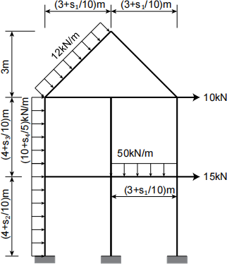
Perform a finite element analysis of the frame using ANSYS. Your report should document the following results:
1. Plot of the deformed shape of the frame.
2. Location and value of the maximum bending moment and deflection.
3. Bending moment diagram.
Note that:
1. Use element type “BEAM 188”
2. The accuracy of your result will increase with the number of elements. You may try to use 2 and 4 elements per member and compare the results.
3. To apply the UDL, following the menu Pre-processor -> Loads -> Define Loads -> Apply -> Structural -> Pressure -> On Beams, and select the elements. Applying pressure on Lines will not work for beams.
4. The bending moment diagrams should be annotated with sufficient data for structural design. They can also be plotted by hand or another piece of software.
Task 2: Programming in MATLAB and Using ANSYS
In this assignment, you will complete a computer program for stress analysis in MATLAB. Three-node triangular (constant strain) elements are to be used. You will use your MATLAB program to analyse the two problems given in this assignment. The commercial software ANSYS will also be used to analyse the second problem. Your analyses should be submitted as a part of the report.
2.1 Finite Element Program in MATLAB
Writing a computer program is one of the best ways to learn the finite element method, but it can be daunting. To help you, the following materials are provided:
1. A MATLAB program for seepage analysis with examples. The documentation on this program is provided with some basic skills on MATLAB.
2. An automatic mesh generator, which is also available in public domain, with examples. The mesh generator will facilitate the application of your computer program to solve real engineering problems.
3. Templates for stress analysis.
All the above files are compressed in the file “CVEN4304.MTLB.CODE.zip”. After downloading this file, you must unpack it WITHOUT changing the names and structures of the folders.
It is highly recommended that you study and understand the program for seepage analysis and the accompanying documentation in the folder “DOCUMENTATION”. It should also be helpful in improving your programming skills in MATLAB.
The documentation provides you with instructions on how to use the computer program for seepage analysis and explanations on the structure of the program, which can be used as a guide to extend it to stress analyses.
Templates for Stress Analysis
All the files that are required for your assignment are stored inside the folders TEMPLATES and CODES.
The folder, TEMPLATES contains three MATLAB functions:
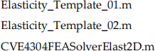
You are recommended to use the file Elasticity_Template_01.m for Problem 1 and the file Elasticity_Template_02.m for Problem 2. Both files are used to input the information of the finite element mesh (in Problem 1) and the geometry (in Problem 2). The formats of these inputs are described in detail in the documentation file accompanying the program CVEN4304.MTLB.CODE. Refer to Section 3 for Problem 1 and Section 4 for Problem 2.
Note to students: There are some differences in the boundary condition input for seepage- and stress- analyses. The format that is required for the stress analysis is described in detail in Elasticity_Template_01.m and in Elasticity_Template_02.m.
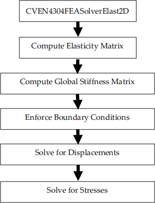
Complete the finite element code in the file CVE4304FEASolverElast2D.m. This file is split into five sections.
You are required to complete the following.
1. Compute Elasticity Matrix
Use the content from the lecture notes. Input the formulae to compute [D] for plane stress and plane strain in the function CVE4304FEASolverElast2D.
2. Compute Element Stiffness Matrix
The global stiffness matrix is obtained from assembling the element stiffness matrices. You are required to complete the functions ElementStiffnessMatrixElasticity2D and ElementBMatrixElasticity2DTri3 which are the codes used for calculating the element stiffness matrix of the constant-strain triangular element. You may use the functions ElementBMatrixSeepage2DTri3 and ElementStiffnessMatrixSeepage2D to aid the structure of your program.
The function PostProcessingElasticity2DTri3 computes the element stresses and plots the displacement and stress contours of the finite element model at the end of the analysis and has already been written for you.
2.2 Stress Analysis Problems
Problem 1
A mesh of triangular elements is shown in the figure with the dimensions, boundary conditions, element numbers (in circles) and nodal numbers (in red). The material has a Young’s modulus E = 30GPa and a Poisson’s ratio v = 0.25. A plane-stress state is assumed.
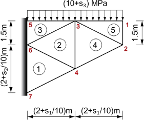
Perform a finite element analysis to determine the nodal displacements and the element stresses. The following items/results must be included in your report:
1. The plot of mesh showing the element and global nodal numbers.
2. The element connectivity table.
3. The nodal coordinates of each element.
4. The B-matrix and element stiffness matrix of Element e (e = 1 for s3 = 1 and 2, e = 2 for s3 = 3 and 4, e = 3 for s3 = 5 and 6, e = 4 for s3 = 7 and 8 and e = 5 for s3 = 9 and 0, where s3 is the third last digit of your student ID).
5. The part of global stiffness matrix related to the free nodes 1, 2, 3 and 4.
6. The solution of nodal displacements.
7. The stresses of Element e (see Item 4).
Problem 2
A concrete structure shown in the figure below carries a lateral pressure and a uniformly distributed vertical load. Assume plane strain condition. Let Young’s modulus E = 25GPa and Poisson’s ratio ν = 0.2. Determine the values and locations of the maximum (in absolute value) horizontal and vertical displacements.
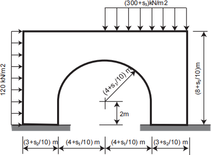
The result of a finite element analysis converges as the mesh becomes finer. It is required in this assignment that you analyse this problem using at least three increasingly fine meshes. This can be done by successively halving the value of “hdata.hmax” inputted to the mesh generator. For example, “hdata.hmax” can be set to 1, 0.5 and 0.25. Although it is not required in this assignment, it is worthwhile to mention that the results obtained from consecutive mesh refinements can be used to perform a convergence study to obtain the “best estimate” and the associated error of the result as explained in Section 9.7 of Cook et al. (2002) “Concepts and Applications of Finite Element Analysis”, 4th edition.
In the file “Elasticity_Template_02.m”, the semi-circle is approximated by line segments. The length of the line segments is chosen to be approximately equal to “hdata.hmax”.
You are also required to use the commercial software ANSYS to analyse this problem. You may choose two meshes in the ANSYS analysis that have similar number of elements to your MATLAB analysis.
Submission
You should submit on Moodle (the files can be zipped into a single file):
1. your MATLAB program,
2. ANSYS database, AND
3. the softcopy of your report.
Please be reminded that it is your responsibility to ensure that your assignment is properly submitted before the deadline for grading. Assignments uploaded in draft form will NOT be graded.
Report
Your report should include the following key contents:
● Title page.
● Table of contents.
● Brief description of the finite element equations that your computer program is based on so that your computer program can be understood and debugged if necessary.
● Printout of the MATLAB function “ElementStiffnessMatrixElasticity2D.m” completed by you.
● The results of your analyses of both problems. For each analysis in Problem 2, the following should be included when applicable:
○ Plot of the finite element mesh.
○ Tabulated displacements at required locations.
○ Plot of displacements.
○ Plot of stresses.
● Conclusions and remarks.
Assessment
The assessment of your assignment is based on the following criteria:
● Completion of your MATLAB program, workout and calculation.
● Quality of the results and documentation of your analysis using your MATLAB program.
● Documentation of your results obtained with ANSYS.
● Clarity and completeness of the report.
2021-11-16