Architecture: Assessed Coursework I 2024
Hello, dear friend, you can consult us at any time if you have any questions, add WeChat: daixieit
Architecture: Assessed Coursework I
Issue date: 9 February 2024. Submission date: 23 February 2024
Question 1 (50 Points, two files to submit)
The processor P1 takes 16-bit instructions. Bits 0-3 are the opcode, bits 4-5 indicate a register in a
register file, and the remaining 10 bits are used as address or data. The architecture of P1 is shown
below. The registers PC, IR, MDR, A1 and A2 retain their value unless their “write” input is 1. When
“ALU control” is 1, the ALU performs A1+A2; otherwise, it performs A1-A2. The register file and the
memory have separate control signals for reading and writing. The “index” input of the register file selects a register. In your answers, control signal should either be set to 0 or to 1. Setting any control signal to “X” will be considered incorrect.
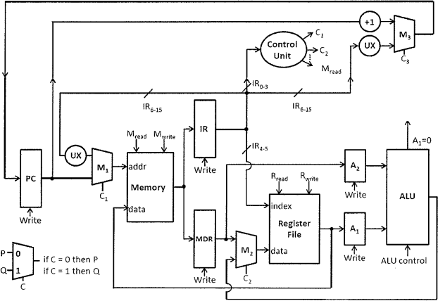
(a) The "load" instruction for P1 takes 3 cycles. In cycle 1, PC is incremented and the instruction is fetched to IR. In cycle 2, bits 6-15 from IR is extended by UX to be a 16-bit address for the memory, and the content from this address is stored in MDR. In cycle 3, the value in MDR is stored in a register in the register file. What are the values of the control signals C1, C2, C3, Mread, Mwrite, Rread, Rwrite etc in each cycle for the “ load” instruction? (25 Points)
(b) The “sub” instruction for P1 subtracts a value in the memory from the value of a register.
The memory address is given by the 10 bits in the instruction. The result is stored back to the register. How many cycles does the “sub” instruction take? What are the values of the control signals in each cycle? (25 Points)
You should answer the two questions by submitting two CSV files namely “q1a.csv” and “q1b.csv” . A template CSV file is provided with this question sheet in the “data file” section. The CSV file can be edited with a spreadsheet processor or a text editor. Please remove unnecessary rows before submission. For example, if your design takes 4 cycles, please remove the rows corresponding to cycle 5 — 10.
Question 2 (50 Points, one file to submit)
The FunnyCore processor has sixteen 32-bit registers. The processor supports the following instructions:
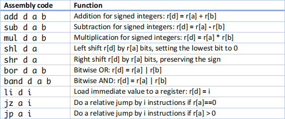
Note that FunnyCore also supports memory instructions, but these instructions are not listed above
because the memory chip is malfunctioning currently. In this table, “d”, “a”, and “ b” are register
identifiers ranging from 0 to 15, specified as decimal numbers; r[k] represents the content of
Register k. Additionally, here is some additional information on the “ li”, “jz”, and “jp” instructions:
. In the “li” instruction, i is an immediate value in the format of a 16-bit signed integer. It
should be specified as a decimal integer in the range -32768..+32767 in the assembly code. This number will be automatically sign-extended before it is loaded into the register.
. In the conditional jumping instructions “jz” and “jp”, the immediate value i is a signed integer. The jump goes forward if i is positive, and backward if i is negative.
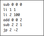
For example, the following piece of code adds up all integers in 1..100, and stores the result in Register 0:
Regarding instruction execution, FunnyCore has the following properties:
. The execution of a “jz” or “jp” or “mul” instruction takes 3 clock cycles; an instruction other than these three only takes 1 clock cycle.
. A numeric overflow or a jump to undefined code will crash the system immediately.
The FunnyCore processor does not support division currently, but the engineering team is considering extending the hardware to support it. A software reference is greatly needed. Please write a piece of assembly code to divide two unsigned numbers. Before the execution of your code, the dividend and divisor are already in Register 0 and 1 respectively. Both the dividend and divisor are 16-bit unsigned integers occupying the lower 16 bits in each register. The higher 16 bits for the two registers are set to 0. The divisor provided to your code will always be positive. You are free to use all 16 registers during the calculation. After calculation, please save the quotient to Register 2 and the remainder to Register 3.
You should put your assembly code in a text file named “q2.txt” . The file should contain no more than 500 lines of assembly code. Your code will be marked from two perspectives:
. Correctness (40 Points). Your code will be tested with 40 dividend/divisor pairs. The correct calculation for each pair brings one point.
. Features (10 Points). You get 10 points if your code supports at least one of the following features:
o Division without restoration.
o Fast execution: on average, your code finishes the division operation within 500 cycles on the tested pairs.
If you have any questions or uncertainties regarding the problem description, please feel free to post them on EdStem.
2024-03-14
computer architecture