ENG2008 Lab exercise 4
Hello, dear friend, you can consult us at any time if you have any questions, add WeChat: daixieit
ENG2008 Lab exercise 4
Interrupts
In this lab exercise the aim is to take the input from a 3x4 keyboard and display the pressed number using the 7-segment display (see lab exercise 3). Refer to lecture noteson GPIO
(Lecture 5) for details of the 3x4 matrix keyboard and how this can be configured to operate with the KL25Z microcontroller. This laboratory is assessed with a lab report describing the design and operation of your system and will contribute 20% towards your overall mark for the module. Further details of the assignment can be found in the assignment brief on ELE and at the end of this document.
A code template is included as a starting point and can be found on the ENG2008 ELE page. You can also buildupon your work in laboratory 3 where appropriate.
Connection of matrix keyboard to KL25Z microcontroller
The pin layout of the keyboard and recommended connection with the KL25Z microcontroller is shown in Fig. 1. Using the protestation breadboard, connect the keyboard as shown in Fig. 1 and the 7-segment display as per lab exercise 3.
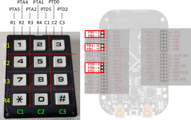
Figure 1. Pin layout of the keyboard and its recommended connection with the KL25Z.
There are two steps to identify which key has been pressed.
Step 1: Determine if any key has been pressed.
• Configure four outputs for four rows (PTA) and three inputs for the three columns (PTD). Enable Port D interrupts for the three column inputs by configuring PCR for these three inputs. Enable the pull up resistors of the three inputs on Port D. The three Port D inputs can be configured using the following code:
PORTD->PCR[n] |= PORT_PCR_MUX(1) | PORT_PCR_PS_MASK | PORT_PCR_PE_MASK | PORT_PCR_IRQC(0x0a);
Note: you must set PCR for EVERY input.
• Write 0s on all the row lines.
• If an interrupt is triggered, a key must have been pressed.
• To test if the interrupt is configured correctly, you can write a code to light up red, green and blue LEDs when any key in columns 1, 2 and 3 is pressed respectively. Or, if you prefer you can use the 7-segment display and display a different output pattern for each column. E.g. “1” for column 1, “2” for column 2 etc.
• If the interrupt works, move on to Step 2.
Step 2: Determine which keys have been pressed.
• Once an interrupt is triggered on Port D, the interrupt handler is called.
• Determine which column line triggers the interrupt by checking the flag in PORTD->ISFR.
• Now configure the four row lines as input.
• The row input will be a logic ‘1’ if the key which is pressed is in that column and logic ‘0’ if it is not.
• Before return from the interrupt handler, make sure the four row lines are configured as outputs, ready for the next detection.
Once the key pressed is determined, display the number using the 7-segment display. You will only need one digit, i.e. only one digit needs to be enabled. The following patterns should be displayed when special keys (* and #) are pressed.
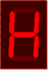 for key * and
 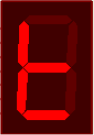 for key #
Your Report
Your report should be a professionally produced (typed not handwritten) record of your experimental work in the laboratory exercise. The report should be limited to a maximum of 6 pages of A4, including figures where necessary, plus an appendix (no page limit) containing your C-code, which should be well commented. The report should explain to the reader the aim of the task, a discussion of the equipment used and an overview of your solution to this problem, including illustrations and/or pictures of the working experiment. Please remember to include figure captions and to refer to the figures in your text where relevant.
The report should consist of the following sections:
1. Introduction [15 marks]
The introduction should provide a brief overview of the background to the project and summarise the main objectives of this laboratory exercise. You can include a brief discussion of microcontrollers and why they are useful for embedded systems.
2. Method [20 marks]
In this section, you should outline what you have done in the laboratory and what equipment have you used? You should include a short discussion about ARM based microcontrollers and the KL25Z board used.
3. Experimental Results and Discussion [40 marks]
Here you should describe, with reference to your attached C-code, how you have programmed the microcontroller to interface with the keyboard and 7-segment display. You should explain the operation of the complete system and include photographs to show the system in operation.
4. Conclusions [5 marks]
Finally, you should conclude the report with a summary of the laboratory. Have you met the objectives? What have you learnt?
5. Appendix [20 marks]
Your C-code must be included as an appendix (not included in 5-page limit). All relevant files should be included and must be well-commented so that the flow of the code and syntax is explained in detail.
2024-03-13