IB3200 Simulation Module 2024: PROJECT BRIEF
Hello, dear friend, you can consult us at any time if you have any questions, add WeChat: daixieit
IB320 Group Work Project Brief 2024
IB3200 Simulation Module 2024: PROJECT BRIEF
Contents
Project Brief Introduction Page 1
System Information Pages 2-4
Tables and Figures Pages 5-7
Project Brief Introduction
John Peters Ltd, a family run manufacturing firm based in the Midlands, wants to increase its efficiency. Their factory floor is set out as shown in Figure 1 (with key in Figure 3). They wish to increase production without a significant increase in costs. The factory floor was originally set up 20 years ago, and they have subsequently updated machinery as parts failed or became obsolete, but the firm has not carried out any comprehensive analysis of the functioning of their factory floor within the last 10 years. In the last few years they have faced increasing competition from new rival firms. They have therefore asked your small consultancy company to come and observe them working. They want your consultancy team to recommend improvements that could be made to theirsystem in order to allow it to run more efficiently. They would ideally like to increase production by at least 20% of current throughput.
Your company colleagues observed and collected information / data about the manufacturing system processes over 3 typical weeks. They have now completed their observations of the factory floor and have provided you with data and information on the various processes within the system. You have been asked to build a DES model of the functioning of the John Peters Ltd factory floor over its opening hours.
The majority of the quantitative data your colleagues collected is shown in the accompanying MSExcel file “IB3200 Group Work Assignment Data” which can be downloaded from my.wbs. The other information gathered by your colleagues about how the manufacturing system functions is contained in the rest of this project brief. Any assumptions / simplifications stated in this document have been previously agreed as reasonable with the client. All the information available for this project is contained in this document and the excel file. Any information / data not provided in this document or the excel file should be considered as unavailable (Category C data). You may decide to make further simplifications, assumptions or parameter estimations as you feel necessary and applicable. Please make all assumptions, simplifications and any parameter estimations very clear in the written report with clear justifications (citing sources if applicable).
The company is open to re-configuring the layout of the machines and staffing. There are also newer machines now available that they could update to. But they do not wish to make significant investments unless it is absolutely necessary. You have been asked to build a DES model of this system in order to explore what resource mix or other changes could allow them to increase throughput and improve efficiency in their manufacturing process.
System Information
Manufacturing procedures:
There are two separate raw materials (RM1 and RM2) required for the manufacturing process. The raw materials are measured in units. Both types of raw materials enter the factory floor separately and begin processing: One unit of RM1 on machine A1 and one unit of RM2 on machine C1. The order in which each type of raw material is processed through the various manufacturing machines on the factory floor can be found in Table 1. Once the raw material has completed processing on the first machine (either A1 or C1) it is referred to as Work In Progress (WP1 from RM1, WP2 from RM2).
There are three machines belonging to Block B. WP1 must be acted upon by each machine in Block B, once only. WP1 enters Block B and starts processing on any machine with equal probability. After that it must progress, in order, around the other machines, as shown in diagram Figure 4. A unit of WP1 exits Block B as soon as it has completed being processed by all 3 machines.
There are three machines belonging to Block D. WP2 enters Block D and muststart processing on D1 first. After that it can progress to either of machines D2 or D3, and needs to be processed by only one of them. When WP exits D1 it is moved into the buffer that currently holds the least amount of WP. It is then processed by the respective machine (D2 or D3). A unit of WP2 exits Block D as soon as it has completed being processed by either D2 or D3.
There is a buffer (storage bin) before each machine of type A, B, C, D and E where RM/WP waits to be processed using a last in, first out queuing discipline. The buffers for A1, C1 and E1 are larger, being able to take a maximum of 200 units each. The other A, B, C and D machine buffers can all take a maximum of 100 units of WP each.
Some machines can only process one unit of RM/WP at a time, whereas other machines can process several units of RM/WP simultaneously. The number of units of RM/WP each machine can process simultaneously can be found in Table 2 (apart from A3, D1 and E1 whose processing is explained in more detail below).
Machine D1 collects two units of WP2 from its buffer and assembles them into one unit of WP that can then move onto either D2 or D3. It can only assemble one pair at a time. Machine A3 does likewise, collecting 2 units of WP1 from its buffer and assembling them into one unit of WP that can then move onto Block B for further processing.
Machine E1 amalgamates one unit of WP1 with one unit of WP2 to produce a finished article. E1 has two separate buffers (one for WP1 and one for WP2) each operating a last in, first out queuing discipline. This E1 machine therefore takes one unit of WP1 from its WP1 buffer along with one unit of WP2 from its WP2 buffer and processes these together. It must take the work in pairs (i.e. it won’t take a unit of WP1 until there is a unit of WP2 available also, and visa versa. Machine E1 can process up to 6 units simultaneously (i.e. 3 pairs of WP1+WP2). After completion on E1, the finished articles are automatically moved into the warehouse packaging department which is not a part of this system analysis and is deemed to be able to cope with any increase in throughput from the factory floor.
The time it takes WP to travel from exiting one machine to entering the buffer of the next machine is 12 seconds.
They currently achieve an average throughput of around 1188 completed articles per day (24 hour period).
Testing procedures:
There are also several testing procedures that check the work in progress as it moves through the manufacturing system. There are three separate testing areas(T1, T2 and T3). T1 consists of a sequence of 2 different testing apparatus. T2 has a sequence of 3 different testing apparatus. T3 has a sequence of 4 different testing apparatus. These testing procedures are carried out following the rules of the external regulator and are not able to be changed in any way by John Peters Ltd. These rules dictate that:
• 1% of WP1 exiting machine A2 is collected and taken to T1 where it undergoes testing to destruction.
• 1% of WP2 exiting machine C3 is collected and taken firstly to T2, from where it moves onto T3. These WP units are also tested to destruction.
It takes between 20 and 30 minutes to test a unit of WP1 in T1, and between 35 and 40 minutes, in total, to test a unit of WP2 in T2-T3. But staff can multitask in order to look after more than one WP unit in the testing areas at any one time. After testing is completed, the destroyed WP are sent to the DA1 area where they are disassembled and made safe, and then sent on for recycling elsewhere. If the testing results point to any calibration/procedural issues within the manufacturing process this is fed back to management immediately, who then oversee re-calibration/amendment of the appropriate machines or staff training. This is done in a way that does not unduly affect throughput rates. The testing and disassembly area can be seen in Figure 2 (key in Figure 3).
Factory Floor Staff:
During operating hours, John Peters Ltd currently maintain an active workforce of:
• 5 staff members on the factory floor at any time.
• 4 staff across the three testing areas and disassembly area at any time.
• 5 staff working in the warehouse at any time.
The company operates a shift system to maintain this coverage. There is also a company secretary, a factory floor manager who does not operate the machines but oversees the running of the manufacturing process and a company director. They work in offices off to the side of the factory floor.
Machines A3, A4, C1, C2, C3 and E1 are totally automatic and do not require a staff member to function. Machines A1, A2, B1, B2, B3, C4, D1, D2 and D3 require a staff member present to be able to function. Currently machines A1, A2, C4, D1, D2 and D3 have a dedicated member of staff assigned to them. But B1, B2 and B3 share two members of staff, who operate all three machines. However, each staff member can only operate one machine at a time. None of the staff operated machines load up with a unit of WP automatically, so a staff member must be available to load the WP onto the machine (i.e. units of WP are not taken out of a machine buffer until a member of staff is available at that machine, if it is a staff operated machine.)
The factory manufacturing floor operates 24 hours, 7 days/week. Shifts work from 8am – 4pm, 4pm – midnight, midnight – 8am. Any set breaks are taken in a way that does not impact the working of the factory floor or the staff coverage required.
Arrival and machine duration data:
RM1 and RM2 arrive from the suppliers on a regular basis and are stored in the company warehouse. The raw materials are then moved into the buffers for A1 and C1 on a regular basis. Currently, the RM is delivered into the buffers for A1 and C1, on the hour, at fixed hourly intervals (e.g. 06:00, 07:00, 08:00 etc..). 100 units of RM1 and 100 units of RM2 are placed into the appropriate buffers at each hourly delivery. If there is not room to input all 100 new units of RM into the buffers for A1 and C1, they are simply topped up to the maximum of 200, and the unused units are taken back to the warehouse.
Data was collected on the machine durations, in minutes. The automatic machines (that do not require human input) have a set duration that they do not deviate from. These durations are shown in Table 3. The processing times for machines A1, D1, D2 and D3 are known to follow the probability distributions as indicated in Table 4.
The processing times for machines A2, B1, B2, B3 and C4 to process one unit of WP were collected, in minutes, and can be found in the accompanying MSExcel file “IB3200 Group Work Assignment_Data” which can be downloaded from my.wbs.
Tables and Figures
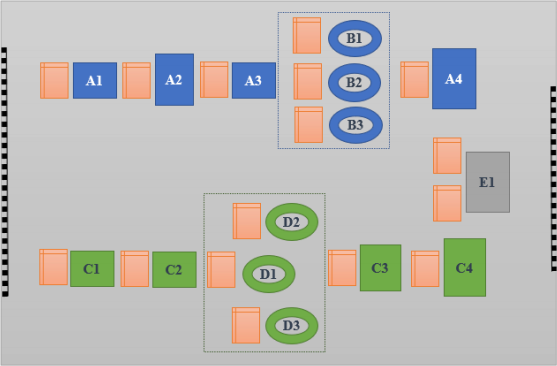
Figure 1: Layout of the factory floor. (Not drawn to scale).
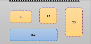
Figure 2: Layout of the Testing and Disassembly area. (Not drawn to scale).
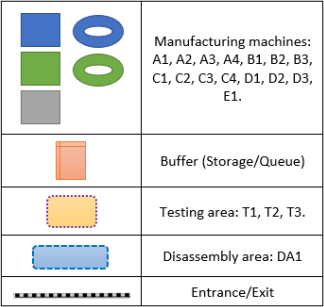
Figure 3: Key for Figures 1 and 2.
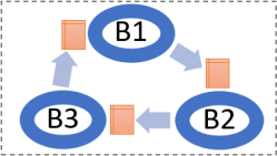
Figure 4: Order of processing in Block B: WP can enter at any point to start processing on any machine, but then must proceed in order around the cycle of the three machines, until it has been processed by each one. It then exits the Block.
Table 1: order of processing of manufacturing.
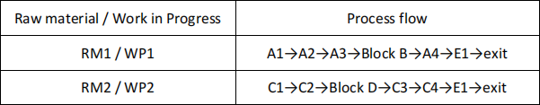
Table 2: Number of RM/WP units a machine can work on simultaneously.
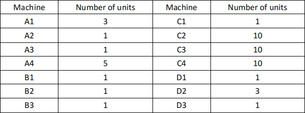
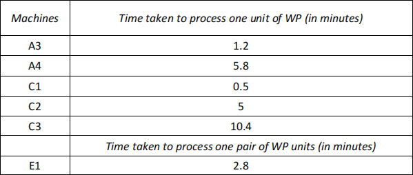
Table 4: Machine durations for A1, D1, D2 and D3 (in minutes)

2024-03-05