ELEC0028 Advanced Digital Design
Hello, dear friend, you can consult us at any time if you have any questions, add WeChat: daixieit
ELEC0028 Advanced Digital Design
Coursework Assignment
Introduction
The aim of this assignment is to write a SystemVerilog description of a RISC-V microprocessor, and simulate its operation using Icarus Verilog.
Download and install Icarus Verilog, GTKWave and Visual Studio Code on your laptop computer, following the instructions in the document ‘Icarus Verilog and GTKWave Installation and User Guide’ on the ELEC0028 Moodle page. (Note: If you used these apps last year on the ELEC0010 course, they may still be working on your computer, and do not need to be reinstalled.)
The deliverable is a report (a pdf file, to be uploaded using the coursework submission tab on the Moodle page). The report should include:
• the SystemVerilog code you have written,
• the simulation results in text form and/or graphical form,
• comments on whether the design functions as expected.
The microprocessor you design should be able to execute all of the subset of RV32I base instructions listed in Table 1.
Table 1: Subset of RV32I base instructions
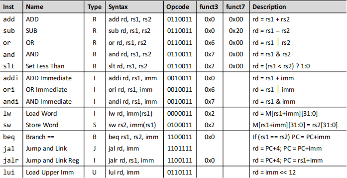
Figure 1 shows the microarchitecture of the processor, which can execute all of the instructions in Table 1. Figure 2 shows the internal circuit design of the microprocessor’s Arithmetic Logic Unit (ALU), and the table of ImmSrc control signal values.
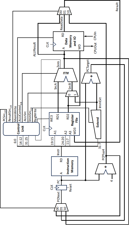
Figure 1 RISC-V microarchitecture
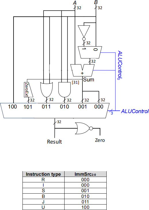
Figure 2 Top: RISC-V Arithmetic Logic Unit (ALU). Bottom: Table of ImmSrc values
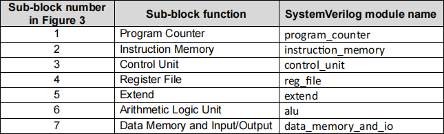
You should create a hierarchical design, with the sub-blocks which are highlighted in Figure 3 implemented as individual SystemVerilog modules. These will then be instantiated by the top-level module, which will have the module name risc_v.
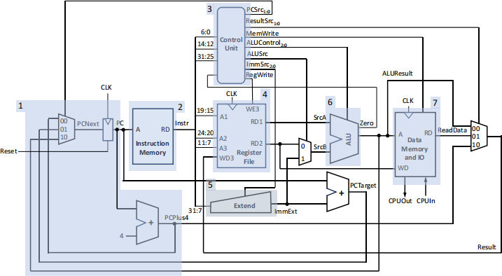
Figure 3 RISC-V microarchitecture with the sub-blocks highlighted
The sub-blocks in Figure 3 are listed in Table 2.
Table 2 RISC-V sub-blocks
List of tasks
Task 1
▪ Copy out and complete Table 3, specifying the control signals for each of the instructions.
Table 3 Table of RISC-V control signals, to copy out and complete
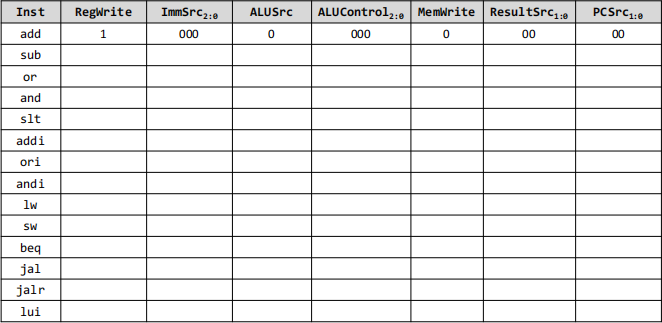
[10 marks]
Task 2
The set of SystemVerilog modules can be found in the folder ‘RISC-V SystemVerilog modules’ on the ELEC0028 Moodle page. Some of the modules are already complete (instruction_memory, reg_file, and data_memory_and_io). The other modules are incomplete. The machine code program is stored in hexadecimal form in a text file (program.txt), which should be saved in the same folder as the SystemVerilog files. An example machine code program is included in the ‘RISC-V SystemVerilog modules’ folder on the Moodle page.
• Study the SystemVerilog code of the completed modules, and note the following:
o The machine code program is written into the array prog in the instruction_memory module using using the $readmemh system task.
o The Instruction Memory and Data Memory are both byte-addressable.
o The input and output of the processor are memory-mapped:
▪ Load word (lw) from data memory address 0xFFFFFFFC causes the input to the microprocessor (CPUIn) to be written into the destination register.
▪ Store word (sw) to data memory address 0xFFFFFFFC causes the value in the source register to be output from the microprocessor (CPUOut).
• Complete the code for the remaining modules (program_counter.sv, control_unit.sv, extend.sv and alu.sv).
o The program counter (PC) register should be updated on the positive edges of the clock, and should have a synchronous active-high reset. Resetting the PC causes the microprocessor to start executing the stored program from memory address 0.
o The entire 32-bit instruction (Instr[31:0]) is input to the extend module. Use the appropriate subset of these bits to generate the extended immediate (ImmExt) output from the extend module.
o In the alu module, describe the ALU’s functionality using a case statement within a combinational cyclic behaviour (always_comb). Addition and subtraction can be described with the SystemVerilog syntax:
sum = a + b; sum = a – b;
respectively. The simulator (and circuits produced by synthesis tools) will automatically use 2’scomplement numbers to represent negative values, and to carry out subtraction.
[25 marks]
Task 3
• Choose a set of test inputs to test each of the modules you have written.
• Write testbenches to test the individual modules, with the testbench names program_counter_tb, control_unit_tb, extend_tb and alu_tb.
• Carry out simulations to test these modules using Icarus Verilog. Present the results in text form and/or graphical form (timing diagrams using GTKWave). Comment on whether each module functions as expected.
[20 marks]
Task 4
• Complete the top-level module (risc_v.sv), interconnecting the individual modules to form the microarchitecture in Figure 3.
o Multiplexers can be described in the top-level module using if..else statements, case statement, or conditional statements, e.g.:
assign mux_out = (select) ? a : b;
o The adder circuit generating PCTarget can be written using the syntax
assign s = a + b;
• Write a testbench, with the name risc_v_tb, to test the risc_v module. The inputs that should be applied to the risc_v module by the testbench are the clock (CLK), reset and CPUIn. The output is CPUOut. Apply the value CPUIn = 32’d8 in the testbench.
• Read through the machine code program in the file ‘program.txt’ provided in the folder in Moodle, and disassemble the program (i.e., write out the program as RISC-V assembly code). Write a description of what you would expect the program to do.
• Compile the complete RISC-V microprocessor design and run the simulation, using Icarus Verilog. Present the results in text form and/or graphical form (timing diagrams using GTKWave). Comment on whether the microprocessor functions as expected.
[25 marks]
Task 5
• Write a RISC-V assembly program which tests each of the assembly instructions in Table 1. Assemble the program (i.e., convert your assembly program to machine code, expressed in hexadecimal), and save the code in the text file ‘program.txt’.
• Compile the complete RISC-V microprocessor design, including your new program, using Icarus Verilog. Carry out the simulation. Present the results in text form and/or graphical form (timing diagrams using GTKWave). Comment on whether the microprocessor functions as expected.
[20 marks]
2024-03-02