Groundwater Resource Investigation CVEN4503 Workshop 2
Hello, dear friend, you can consult us at any time if you have any questions, add WeChat: daixieit
Groundwater Resource Investigation CVEN4503 Workshop 2
Workshop #2 - Individual assignment #1
Complete all tasks and answer all questions contained in this document. Use graph paper and additional sheets as necessary.
Assessment information and submission instructions:
- This assignment is due on 27th February 2024 at 9 am.
- Submit into the Moodle online Week 2 Assignment Hand-in Box
- This assignment is worth 20% of the course mark.
- Please keep a copy of what you submit!
- Do not send by email as this will not be accepted!
Workshop tasks and questions
1. A sequence of horizontal sandstones and shales is known to exist beneath a site. The surface topography is varied with hills and valleys. Four bores have been drilled at the locations shown in Table 1.
Table 1.
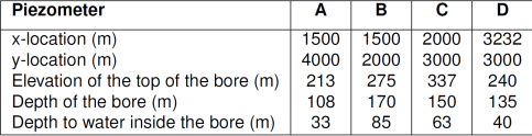
The bores have each been completed as a piezometer with a screen set in a sandstone unit. The sandstone unit is known to be 3 m thick but unfortunately, all other records have been lost!
Answer the following: (20 points)
(a) Draw a sketch to show the relationship of the bores in plan (x-y).
(b) Draw a sketch section to show the main aquifer (x-z), include the hydraulic heads.
(c) What is the horizontal hydraulic gradient and the direction of flow in the main aquifer? Hint, plot the hydraulic heads in (a)
(d) If the transmissivity of the sandstone unit is 250 m2 /day what is the horizontal flow through a 1000 m wide section of this sandstone unit?
2. Groundwater time series analysis (35 points)
On Moodle you will find three spreadsheets with groundwater level data from a nested borehole (BH22 – see Figure 1) in the upper Maules Creek catchment. The timeseries data are from non-vented loggers and they will therefore have to be corrected for variations in air pressure (barometric pressure). You are therefore also provided with a barometric timeseries for the same period. The groundwater pressure timeseries data are provided in the units of mH2O, while the barometric data are in the units of kPa (kilo Pascal). As the pressure data are relative you are also provided with manual water level measurements (dip data to be found in file: Dip data.xls) and bore elevation reference (see Figure 1). This allows you to convert the pressure data to absolute groundwater level (i.e., relative to meters Australian Height Datum – mAHD).
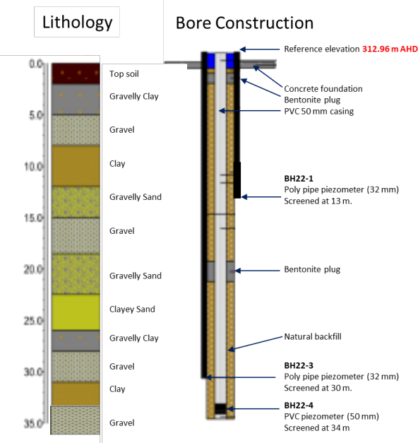
Figure 1: Lithology and bore construction of Borehole BH22 in the upper Maules Creek catchment. Note the reference elevation at the top of the borehole is 312.96 m AHD.
(a) Convert the barometric data from kPa to mH2O and correct the water level logger data from borehole BH22-1, BH22-3 and BH22-4 for barometric effects. Hint, note that the different timeseries may not all have the same start or stop times, so ensure that the time stamp aligns for each row when combining data from different spreadsheets.
(b) Using the dip data for each bore and the bore reference elevation, convert each timeseries to absolute water level [mAHD].
(c) Provide an equation, or a set of equations, explaining what you did in part (a) and (b).
(d) Plot all the converted data together in a graph as a function of time. Hint, in Excel add the date and time columns together in a new column and chose the short date format.
(e) Provide an interpretation of what is happening with the groundwater levels in the nested borehole. Hint, use the provided rain fall data and the bore log in Figure 1.
(f) Calculate the water flux and direction between BH22-3 and BH22-4. Provide an estimate of the uncertainty and state all your assumptions.
3. Groundwater resource assessment: (45 points)
The Maules Creek catchment is located at the foothills of the Nandewar Range which is of volcanic origin and located in the semi-arid North-western Slopes and Plains district of New South Wales. The highest peak along the range is Mt Kaputar (1500 mAHD). The Namoi River is an intermittently flowing stream in the catchment and receives run-off from the mountains through Maules Creek (Figure 2).
The lower part of the catchment comprises some of the most fertile soils in Australia. Intense agriculture has therefore been developed since the 1960’s. Due to the semi-arid climate the rainfall is uncertain, and farmers have been pumping groundwater since the 1980’s to irrigate their crops.
Table 3 contains information about the groundwater monitoring boreholes shown in Figure 2 located within the Maules Creek catchment. Groundwater levels have been monitored in this catchment for decades. The manual groundwater dips measured in each borehole are provided for January 1978 and 2007 only.
Complete the following tasks:
(a) Calculate the hydraulic heads for all boreholes provided in Table 2 for the year 1978 and 2007. Make your own table to hand in. Hint: A ’dip’ is the distance between the top of the borehole and the water table in the borehole!
(b) Complete a groundwater hydraulic head transect across the Namoi River by adding the relevant hydraulic heads for 1978 and 2007 to Figure 3 (provided in this assignment).
(c) Construct horizontal groundwater hydraulic head contours (flow nets) by hand using the hydraulic heads for the years 1978 and 2007. Use Figure 4 as a template for the flow net for the year 1978, and Figure 5 for the year 2007. Indicate approximate locations of any groundwater sources and sinks, and clearly mark the general flow direction.
(d) Estimate and compare the Darcy flow rate between borehole 34 and 35 for the years 1978 and 2007 assuming an average hydraulic conductivity of K = 5 ×10⁻⁵ m/s.
(e) Estimate the volumetric groundwater resource depletion per meter width along the transect between the years 1978 and 2007 assuming a specific yield of Sy = 0.25. Hint: The result is based on a transect so the units are m3 /m.
(f) Explain qualitatively how the Namoi River may be affected by the agricultural development between 1978 and 2007 using Figure 3 as a guide.
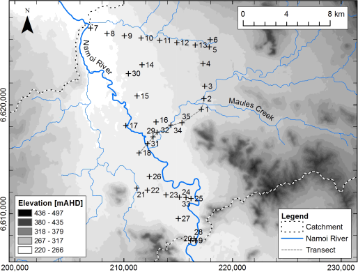
Figure 2: Map of the Maules Creek catchment with groundwater borehole and transect locations marked. x-axis (bottom) is Easting in meters, y-axis (left) is Northing in meters. Note the transect that is plotted as a dashed line (see legend) between boreholes 18 and 2 (refer to Figure 3).
Table 2: Groundwater borehole locations (for Easting and Northing refer to Figure 2), elevations and manual water level dips (m below borehole casing) for January of the years 1978 and 2007.
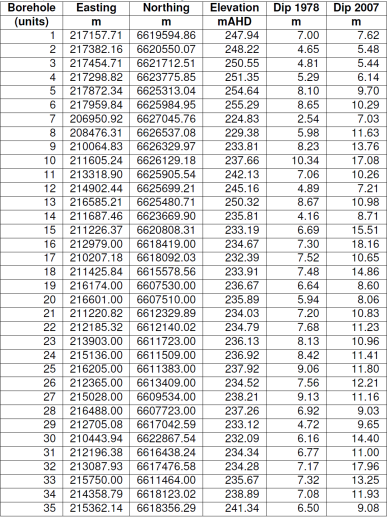
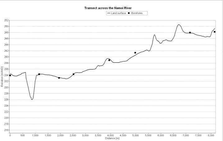
Figure 3: Transect across the Namoi River along Maues Creek (for location see Figure 2). Use this figure to draw the groundwater heads along the transect for 1978 and 2007.
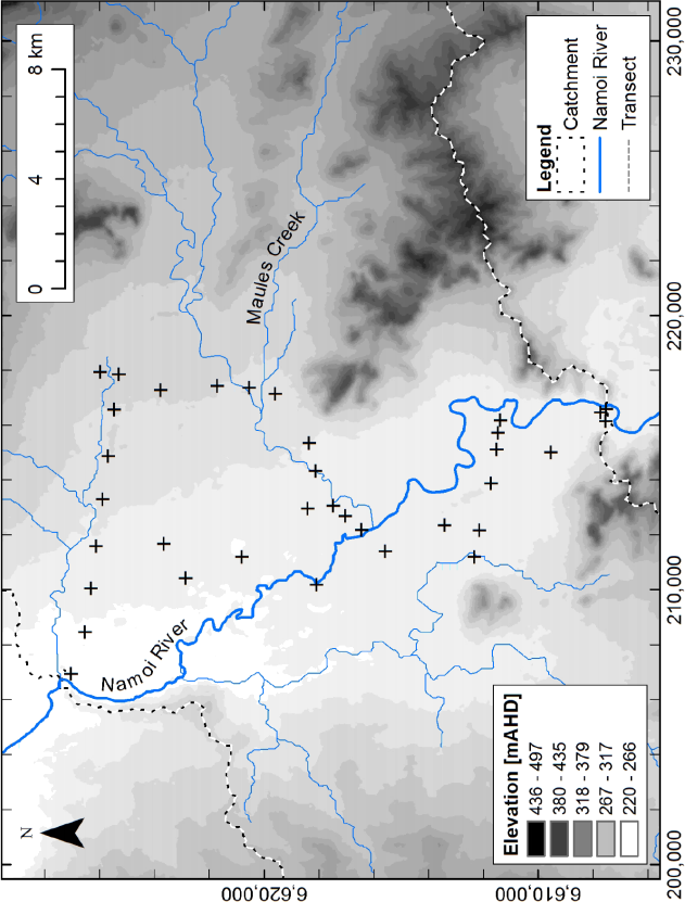
Figure 4: Use this figure to draw the horizontal groundwater flow net in the year 1978 from data in Table 2.

Figure 5: Use this figure to draw the horizontal groundwater flow net in the year 2007 from data in Table 2.
2024-02-25