Assignment 2 – Analysis of Deflection in Simply Supported Beam
Hello, dear friend, you can consult us at any time if you have any questions, add WeChat: daixieit
Assignment 2 – Analysis of Deflection in Simply Supported Beam
1. Objectives
To learn how to measure wavelength by FBG.
To learn how to transfer wavelength into strain.
To learn how to calculate Young’s modulus E of certain materials.
To learn how to compute the stress and strain of a simply supported beam.
To analyze the differences between measured data and theoretical solutions.
2. Experiment
2.1 Apparatus
The experimental setup shown in Fig. 1 and Fig. 2 includes a loading frame, dial gauge, hangers, standard weights, FBGs, data logger, and beam specimens.
The hangers will be placed at the trisection points of the beam. The dial gauge is used to measure the deflection at the mid-point of the beam. The FBGs will be attached to both the top and bottom surfaces of the beam at the mid-point.

Fig. 1 Schematic of the experimental setup
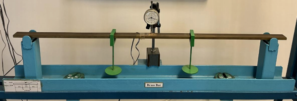
Fig. 2 The experimental setup
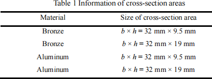
The materials used in the experiment are bronze and aluminum steel. The length of the beam is L = 915 mm, and there are four different cross-section areas, as shown in Table 1.
The Young’s modulus (Elastic modulus, E) of each material is unknown, and it can be calculated in the following steps. The weight will be added to the two hangers.
2.2 Procedure
a) Measure the dimensions of the beams. (The data will be directly given to you.)
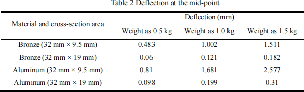
b) Carry out simple bending tests on one beam. Add weights (three weights i.e., 0.5 kg, 1.0kg, and 1.5kg) to the two hangers and record the deflection at the mid-point (experiment results by dial gauge are given in Table 2) and the wavelengths captured by the FBGs on the top and bottom surfaces of the beam at the mid-point.
c) Transfer the wavelength into strain.
d) Calculate the material properties, i.e. the moment of inertia I of the cross-section of the beam and Young’s modulus E of the material using the following equations:
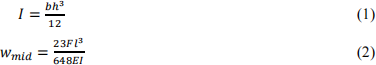
where wmid is the deflection in the mid-point, b is the width of the cross-section, h is the height of the cross-section, l is the length of the beam, and F is the load.
e) Compute the bending stress σ and strain ε of the simply supported beam according to the bending theory. You can use the following equations:
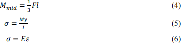
where Mmid is the moment in the mid-point, y is the distance between each surface of the beam and the neural axis (in this case, y = h / 2).
f) Compare the measured data and the theoretical result. Then analyze and discuss the reasons why there are differences between them.
2.3 Discussion
a) Please analyze the measured data, and calculate the moment of inertia, Young’s modulus, the stress, and the strain.
b) Please compare the differences between experimental data (both the FBG data and dial gauge data) and theoretical results and discuss why.
2024-02-24