EEEE4121 Distributed Generation and Alternative Energy Description of Coursework #1 (2024)
Hello, dear friend, you can consult us at any time if you have any questions, add WeChat: daixieit
EEEE4121 Distributed Generation and Alternative Energy
Description of Coursework #1 (2024)
Design and evaluation by simulation of a standalone PV system with battery storage with increased security of electrical power supply
This project aims at designing a PV system able to provide the full daily electrical energy demand of a critical single phase AC consumer (240Vrms/50Hz), therefore being able to work in a standalone mode in the case of a prolonged loss of public electricity network with the help of battery energy storage. The connection of the PV panel string to the DC link of the H-bridge inverter should follow the suggestion in Fig 1, whilst the configuration of the battery stack is not imposed in anyway. It could be in the DC link of the H-bridge inverter via a separate DC/DC converter or independently to the AC side via its own DC/AC bidirectional inverter, but the topology choice of the battery converter needs to discussed in report.
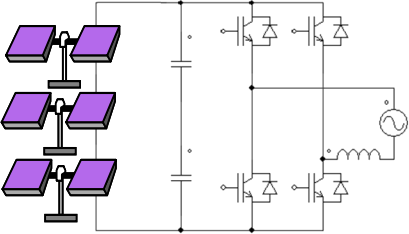
Fig. 1. Single Stage Power Electronic Interface to connect a PV panel string to the AC power grid.
The project will consist of the following parts:
Part 1. You will be given a load power profile and the orientation and inclination of a rooftop of a building on which the PV panels will have to be installed. You will be given a specific month of the year for which the energy captured during a sunny day (https://re.jrc.ec.europa.eu/pvg_tools/en/) should cover the energy consumed as resulting from the load power profile given. A sample of the PV panel datasheet used in the design exercise is provided in moodle as a model but for full marks you need to identify a solar panel that should be used to implement the PV string that would give you sufficient string voltage to allow connection to the DC link of the H-bridge inverter whilst avoiding overmodulation.
You may assume the PV power available at a given moment in time [i] is proportional with the time dependent illumination data (input from CSV file) relative to the nominal illumination stated in the datasheet (typically 1000W/m2 for standard operating condition) and multiplied by the PV panel rating:, as follows:
Ppv [i] = Pmpp@1kW/m2* CSV file_illum [i] / Datasheet_nom_ilum@1kW/m2 (1)
You need to insert the relevant graphs from PV panel datasheet in the report (state also the web link also to the datasheet in reference!!).
For validation of the PV string configuration, you should use the PLECS model provided and customised with individual calculated data as resulted from the individual set of parameters received by each student.
Full marks will be awarded to the designs where the selection of PV panel resulted in a reasonable fit which means that the PV energy collected is only slightly larger (by not more than 30%) than the energy consumed by load and the open circuit voltage of the PV string is not larger than 600V. Also, changes in PV characteristics affecting operation (open circuit voltage, MPP voltage and power) due to temperature should be considered.
Part 2. In order to provide the standalone capability needed to increase the energy security of the critical load, a battery stack is to be sized to compensate for the instantaneous mismatches of power between the PV generation side and the consumer as defined by the load power profile both in terms of available energy but also maximum power stresses (you need to check both during charging and discharging!). The connection of the battery stack to the inverter is not imposed by a specific power converter topology. Students are expected to select a suitable battery chemistry that may suit the specifics of charge discharge cycle (you may consider Li-ion, NiMH or lead acid battery, either looking at the datasheets of already built battery modules, or single cells), and calculate the number of modules or cells needed to achieve the energy requirement. For full marks you are also expected to consider aspects related to lifetime, cost and of how to connect the battery to the power system by considering voltage limits emerging from the operation of the power converter that you can choose from the following alternatives:
(i) interface the battery via its own DC/AC inverter directly to the Ac grid, in which case the minimum voltage restriction to avoid inverter modulation applies also to the battery string
selection (no of series connected cells or modules)
(ii) connection of the battery to the DC link of the PV inverter via a:
a. bidirectional voltage step-up (boost) DC/DC converter or
b. bidirectional voltage step down (buck) DC/DC converter.
This selection needs to be justified and the V/I ratings of switches used in the battery converter and should be derived according to worst case conditions. You need to show an electric circuit diagram (not block diagram!) as detailed as possible of the full system and explain how would work.
Part 3. Based on the peak MPP PV power and voltage and its corresponding current delivered by the PV string is identified and validated in Part 1, a more detailed design study will be carried out to calculate the size of passive components (AC side inductance and DC-link capacitance) needed for the single phase H-bridge inverter to connect the PV string designed in Part 1 to the 240Vrms/50Hz single phase grid. This is then followed by a validation by a PLECS simulation study to confirm that the current and voltage ripples are below the limits.
Each student will receive an individual value for the switching frequency, maximum current ripple in AC inductor and maximum DC link voltage ripple across DC link capacitors but it is expected that the target DC- link voltage used in the H-bridge calculations to be the optimum MPP voltage of the PV string (and not the minimum limit!!).
The maximum peak to peak switching current ripple in the AC side inductor is a given percentage (individual value received by email) of the peak of the required fundamental AC side current component which should match the MPP of your PV string.
The maximum peak to peak DC-link voltage ripple is a given percentage (individual value received by email) of your MPP PV string voltage.
2024-02-21