CSS422 Final Project: Thump-2 Implementation Work of C Standard Library Functions
Hello, dear friend, you can consult us at any time if you have any questions, add WeChat: daixieit
CSS422 Final Project
Thumb-2 Implementation Work of Memory/Time-Related C Standard Library Functions.
1. Objective
You’ll understand the following concepts at the ARM assembly language level through this final project that implements memory/time-related C standard library functions in Thumb-2.
• CPU operating modes: user and supervisor modes
• System-call and interrupt handling procedures
• C to assembler argument passing (APCS: ARM Procedure Call Standard)
• Stack operations to implement recursions at the assembly language level
• Buddy memory allocation
This document is quite dense. Please read it as soon as the final project spec. becomes available to you.
2. Project Overview
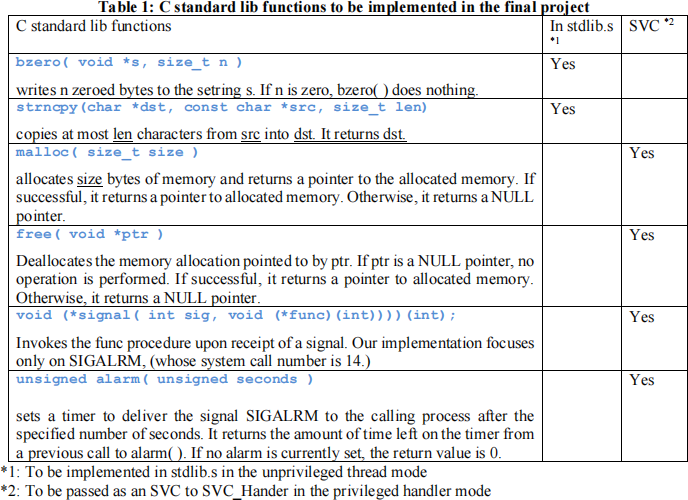
Using the Thumb-2 assembly language, you will implement several functions of the C standard library that will be invoked from aC program named driver.c. See Table 1. These functions must be code in the Thumb- 2 assembly language. Some of them can be implemented in stdlib.s running in the unprivileged thread mode (=user mode), whereas the others need to be implemented as supervisor calls, (i.e., in the handler mode = supervisor mode). For more details, log in one of the CSS Linux servers and type from the Linux shell:
man 3 function where function is either bezro, strncpy, malloc, free, signal, or alarm
The driver.c we use is shown in listing 1. It tests all the above six stdlib functions. Please note that printf() in the code will be removed when you test your assembly implementation, because we won’t implement the printf( ) standard function.
Listing 1: driver.c program to test your implementation
#include
#include
#include
#include
#include
int* alarmed;
void sig_handler1( int signum ) {
*alarmed = 2;
}
void sig_handler2( int signum ) {
*alarmed = 3;
}
int main( ) {
char stringA[40] = "0123456789ABCDEFGHIJKLMNOPQRSTUVWXYZabc\0";
char stringB[40];
bzero( stringB, 40 );
strncpy( stringB, stringA, 40 );
bzero( stringA, 40 );
printf( "%s\n", stringA );
printf( "%s\n", stringB );
void* mem1 = malloc( 1024 );
void* mem2 = malloc( 1024 );
void* mem3 = malloc( 8192 );
void* mem4 = malloc( 4096 );
void* mem5 = malloc( 512 );
void* mem6 = malloc( 1024 );
void* mem7 = malloc( 512 );
free( mem6 );
free( mem5 );
free( mem1 );
free( mem7 );
free( mem2 );
void* mem8 = malloc( 4096 );
free( mem4 );
free( mem3 );
free( mem8 );
alarmed = (int *)malloc( 4 );
*alarmed = 1;
printf( "%d\n", *alarmed);
signal( SIGALRM, sig_handler1 );
alarm( 2 );
while ( *alarmed != 2 ) {
void* mem9 = malloc( 4 );
free( mem9 );
}
printf( "%d\n", *alarmed);
signal( SIGALRM, sig_handler2 );
alarm( 3 );
while ( *alarmed != 3 ) {
void* mem9 = malloc( 4 );
free( mem9 );
}
printf( "%d\n", *alarmed);
return 0;
}
This driver program repeats allocating and deallocating memory space and thereafter sets the sig_handler1( ) function to be called upon receiving the first timer interrupt (in 2 seconds) and sig_ahndler2( ) function to be called upon the second timer interrupt (in 3 seconds).
3. System Overview and Execution Sequence
3.1. Memory overview
This project maps all code to 0x0000.0000 – 0x1FFF.FFFF in the ARM’s usual ROM space (as the Keil C compiler/ARM assembler does) and defines a heap space; user and SVC stacks; memory control block (MCB) to manage the heap space; and all the SVC-related parameters over 0x2000.1000 – 0x2000.7FFF in the ARM’s usual SRAM space. See table 2.
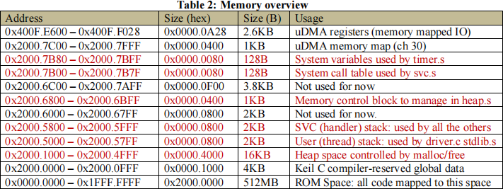
Since we compiledriver.c together with our assembly programs, the Keil C compiler automatically reserves driver.c-related global data to some space within 0x2000.0000 – 0x2000.0FFF, which makes it difficult for us to start Master Stack Pointer (MSP) exactly at 0x2000.6000 toward to the lower address as well as to start Process Stack Pointer (PSP) at 0x2000.5800. So, it’s sufficient to map MSP and PSP around 0x2000.6000 and 0x2000.5800 respectively. For the purpose of this memory allocation, you should declare the space as shown in listing 2:
Listing 2: The memory space definition in Thumb-2
Heap_Size EQU 0x00005000
AREA HEAP, NOINIT, READWRITE, ALIGN=3
heap_base
Heap_Mem SPACE Heap_Size
heap_limit
Handler_Stack_Size EQU 0x00000800
Thread_Stack_Size EQU 0x00000800
AREA STACK, NOINIT, READWRITE, ALIGN=3
Thread_Stack_Mem SPACE Thread_Stack_Size
initial_user_sp
Handler_Stack_Mem SPACE Handler_Stack_Size
initial_sp
3.2. Initialization, system call, and interrupt sequences
(1) Initialization: the ARM processor reads the first 8 bytes to set MSP and the next 8 bytes to jump to the Reset_Handler routine (as you studied in the class). You don’t have to change the original vector table. Reset_Handler initializes all the data structures you’ve developed and finally calls __main with listing 3.
Listing 3: The last two instructions in Reset_Handler (startup_TM4C129.s)
LDR R0, = main
BX R0
These last two statements are from the original startup_TM4C129.s. Then, the main( ) function in driver.c is invoked.
(2) System calls: whenever main( ) calls any of stdlib functions including bzero,strncpy, malloc, free, signal, and alarm, the control needs to move to strlib.s. In other words, you need to define these function protocols in strlib.s, as shown in listing 4:
Listing 4: The framework of stdlib.s
AREA |.text|, CODE, READONLY, ALIGN=2
THUMB
EXPORT _bzero
_bzero
; Implement the body of bzero( )
MOV pc, lr ; Return to main( )
EXPORT _strncpy
_strncpy
; Implement the body of strncpy( )
MOV pc, lr ; Return to main( )
EXPORT _malloc
_malloc
; Invoke the SVC_Handler routine in startup_TM4C129.s
MOV pc, lr ; Return to main( )
EXPORT _free
_free
; Invoke the SVC_Handler routine in startup_TM4C129.s
MOV pc, lr ; Return to main( )
EXPORT _signal
_signal
; Invoke the SVC_Handler routine in startup_TM4C129.s
MOV pc, lr ; Return to main( )
EXPORT _alarm
_alarm
; Invoke the SVC_Handler routine in startup_TM4C129.s
MOV pc, lr ; Return to main( )
END
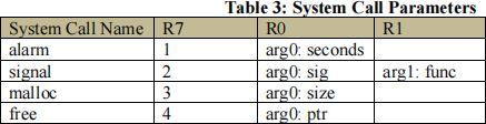
Among these six stdlib functions, you’ll implement the entire logic of bzero( ) and strncpy( ) as they may be executed in the user mode. However, the other four functions must be handled as a system call. You need to invoke SVC_Handler in startup_TM4C129.s. Based on the Linux system call convention, use R7 to maintain the system call number. Arguments to a system call should follow ARM Procedure Call Standard, as summarized in table 3.
SVC_Handler must invoke _systemcall_table_jump in svc.s. This in turn means you must prepare the svc.s file to implement _systemcall_table_jump. This function initializes the system call table in _systemcall_table_init as shown in Table 4:
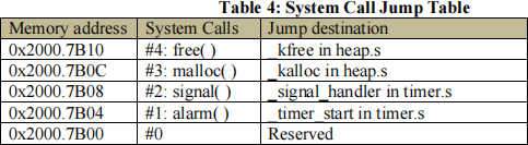
Each table entry records the routine to jump. For this purpose, svc.s needs to import the addresses of these routines, using the code snippet shown in listing 5:
Listing 5: Entry points to kernel functions imported in svc.s IMPORT _kfree
IMPORT _kalloc
IMPORT _signal_handler
IMPORT _timer_start
When called from SVC_Handler, _system_call_table_jump checks R7, (i.e., the system call#) and refers to the corresponding jump table entry, and invokes the actual routine. The merit of using svc.c is to minimize your modifications onto startup_TM4C129.s.
(3) Interrupts: This final project only handles SysTick interrupts. The SysTick timer gets started with _timer_start that was invoked when main( ) calls alarm( ). Note that SysTick timer can countdown up to 1 second. Therefore, if main( ) calls alarm( 2 ) or alarm( 3 ), you’ll get a SysTick interrupts at least twice or three times. Upon receiving a SysTick interrupt, the control jumps to SysTick_Handler in startup_TM4C129.s. The handler routine will invoke _timer_update in timer.s to decrement the count provided by alarm( ), to check if the count reached 0, and if so to stop the timer as well as invoke func specified by signal( SIG_ALRM, func ).
3.3. Structure of your library implementation
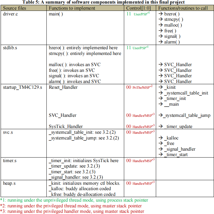
The software components you need for this final project are summarized in table 5.
4. Buddy Memory Allocation and Test Scenario
The final project implements the buddy memory allocation in Thumb-2.
4.1. Algorithms
If you have already taken CSS430: Operating Systems, have your OS textbook in your hand and read Section 10.8.1 Buddy System. Since the CSS ordinary course sequence assumes CSS422 taken before CSS430, here is a copy of Section 10.8.1:
10.8.1 Buddy System
The buddy system allocates memory from a fixed-size segment consisting of physically contiguous pages. Memory is allocated from this segment using a power-of-2 allocator, which satisfies requests in units sized as a power of 2 (4 KB, 8 KB, 16 KB, and so forth). A request in units not appropriately sized is rounded up to the next highest power of 2. For example, a request for 11 KB is satisfied with a 16-KB segment.
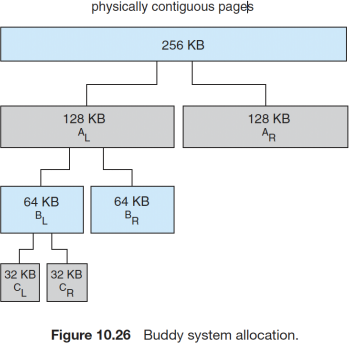
Let’s consider a simple example. Assume the size of a memory segment is initially 256 KB and the kernel requests 21 KB of memory. The segment is initially divided into two buddies—which we will call AL and AR—each 128 KB in size. One of these buddies is further divided into two 64-KB buddies—BL and BR. However, the next-highest power of 2 from 21 KB is 32 KB so either BL or BR is again divided into two
32-KB buddies, CL and CR. One of these buddies is used to satisfy the 21-KB request. This scheme is illustrated in Figure 10.26, where CL is the segment allocated to the 21-KB request.
An advantage of the buddy system is how quickly adjacent buddies can be combined to form larger segments using a technique known as coalescing. In Figure 10.26, for example, when the kernel releases the CLunit it was allocated, the system can coalesce CL and CR into a 64-KB segment. This segment, BL, can in turn be coalesced with its buddy BR to form a 128-KB segment. Ultimately, we can end up with the original 256-KB segment.
The obvious drawback to the buddy system is that rounding up to the next highest power of 2 is very likely to cause fragmentation within allocated segments. For example, a 33-KB request can only be satisfied with a 64-KB segment. In fact, we cannot guarantee that less than 50 percent of the allocated unit will be wasted due to internal fragmentation. In the following section, we explore a memory allocation scheme where no space is lost due to fragmentation.
4.2. Implementation over 0x20001000 - 0x20004FFF
As the memory range we use is 0x20001000 – 0x20004FFF, the entire contiguous size is 16KB. This space will be recursively divided into 2 subspaces of 8KB, each further divided into 2 pieces of 4KB, all the way to 32B. Therefore, one extreme allocates 16KB entirely at once, whereas the other extreme allocates 512 different spaces, each with 32 bytes. To address this finest case, (i.e., handling 512 spaces), we allocate a memory control block (MCB) of 512 entries, each with 2 bytes, in the 1KB space over 10x20006800 – 0x20006BFF. Each entry corresponds to a different 32-byte heap space. For instance, let MCB entries are defined as
short mcb[512];
Then, mcb[0] points to the heaps space at 0x20001000, whereas mcb[511] corresponds to 0x20004FE0. However, each mcb[i] does not have to manage only 32 bytes. It can manage up to a contiguous 16KB space. Therefore, each mcb[i] has the size information of a heap space it is currently managing. The size can be 32 bytes to 16KB and thus be represented with 5 to16 bits, in other words with mcb[i]’s bits #15 - #4. We also use mcb[i]’s LSB, (i.e., bit #0) to indicate if the given heap space is available (= 0) or in use (= 1). Table 6 shows each mcb[i]’sbit usage:
Table 6: each mcb entry’sbit usage
|
bits |
descriptions |
|
#15 – #4 |
The heap size this mcb entry is currently managing |
|
#3 – #1 |
Reserved |
|
#0 |
0: available, 1: in use |
Let’s consider a simple memory allocation scenario where main( ) requests 4KB and thereafter 8KB heap spaces with malloc( 4096 ) and malloc( 8192 ). Based on the buddy system algorithm, this scenario allocates 0x2000100 – 0x20001FFF for the first 4KB request and 0x20003000 – 0x20004FFF for the second 8KB request. Figure 1 shows this allocation. Only mcb[0], mcb[128], and mcb[256] are used to indicate in-use or available spaces. All the other mcb entries are not used yet.
|
Heap Address |
Memory Availability |
|
MCB |
MCB Address |
Contents |
|
0x20001000 – 0x20001FFF |
4KB in use |
|
mcb[0] |
0x20006800 |
409710 (0x1001) |
|
0x20002000 – 0x20002FFF |
4KB available |
|
mcb[128] |
0x20006900 |
409610 (0x1000) |
|
0x20003000 – 0x20003FFF |
8KB in use |
|
mcb[256] |
0x20006A00 |
819310 (0x2001) |
|
0x20004000 – 0x20004FFF |
Figure 1: heap space and mcb contents
4.3. Implementation
For each implementation of_kinit, _kalloc, and _kfree, refer to figure 2 that illustrateshow mcb entries are updated.
(1) _kinit: The initialization must writes 1638410 (0x4000) onto mcb[0] at 0x20006800-0x20006801, indicating that the entire 16KB space is available. All the other mcb entries from 0x20006802 to 0x20006BFE must be zero-initialized (step 1 in figure 2).
(2) _kalloc: Your implementation must use recursions. When _kalloc( size ) is called with a size requested, it should call a helper function, say _ralloc, as recursively choosing the left half or the right half of the current range until the requested size fits in a halved range. For instance in figure 1, the first malloc( 4096 ) call is relayed to _kalloc( 4096 ) that then calls _ralloc( 4096, mcb[0], mcb[511] ) or _ralloc( 4096, 20006800, 20006BFE ). See step 2 in figure 2. The _ralloc call finds mcb[0] at 0x20006800 has 16384B available, halves it, and chooses the left half by calling itself with _ralloc( 4096, mcb[0], mcb[255] ) or _ralloc( 4096, 2006800, 200069FE ). At this time, make sure that the right half managed by mcb[256] at 0x20006A00 must be updated with 8192 as its available space (step 3). Since the range is still 8192 bytes > 4096 bytes, _ralloc chooses the left by calling itself with _ralloc( 4096,mcb[0], mcb[127] ) or _ralloc( 4096, 20006800, 200068FE ). Make sure that the right half managed by mcb[128] at 0x2006900 is updated to 4096. The left half in the range between mcb[0]-mcb[127] or 0x20006800-200068FF fits the requested size of 4096. Therefore, ralloc( ) records 409710 (0x1001) intomcb[0] at 0x20006800-0x20006801. This is step 4 in figure 2.
The second malloc( 8192 ) is handled as follows: _kalloc( 8192 ) calls _ralloc( 8192, mcb[0], mcb[511] ) or _ralloc( 8192, 20006800, 20006BFE ) as in step 5 that needs to choose the right half with _ralloc( 8192, 20006A00, 20006BFE ), because mcb[0] at 0x20006800-0x2006801 has a value of 4097 indicating that the left half (20006800 – 200069FE ) is in use. Since mcb[256] at 0x20006A00-0x20006A01 is available, _ralloc saves 8193 (0x2001) there (step 6).
(3) _kfree: Your _kfree implementation must use recursions, too. The _kfree( *ptr ) function calls a helper function, _rfree( the corresponding mcb[] ). If main( ) calls free( 20001000 ), it is relayed to _kfree( 20001000 ) that calls _rfree( mcb[0] ) or _rfree( 20006800 ) to reset its bit #0 from in-use to available (step 7). Then, check its right buddy at mcb[128] (or 0x20006900). If its bit #0 is 0, indicating the availability, zero-reinitialize mcb[128] at 0x20006900 and make sure that mcb[0] at 0x20006800 shows an availability of 8192 bytes (step 8). Recursively check the buddy at higher layers. So, the next higher layer’s buddy is mcb[256]-mcb[511] at 0x2006A00-0x2006BFE. Check mcb[256]’s contents, (at 0x20006A00-0x20006A01). In figure 2, the content is 8193 or (0x2001), showing that 8KB is being occupied. Therefore, stop _kfree’s recursive calls.
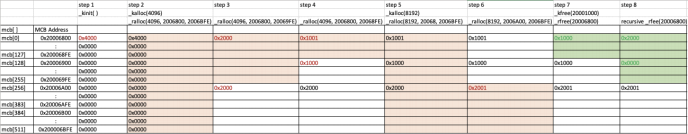
Figure 2: Recursive _ralloc/_rfree calls, each updating mcb entries
4.4. Test Scenario
Looking back to listing 1. “driver.c”, you are supposed to verify your Thumb-2 implementation of malloc( ) and free( ) with repetitive system call invocations that allocate/deallocate mem1 – mem8 spaces. Figure 2 illustrateshow the heap space is allocated and deallocated when you run driver.c. Orange indicates allocated spaces and green means de-allocated spaces.
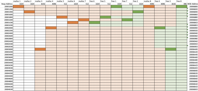
Figure 2: Test scenario and memory allocation
5. Signal and Alarm
The time management you will implement in your final project includes signal( sig, *func ) and alarm( seconds ). The parameters *func and seconds should be memorized in memory address at 0x20007B84 and 0x20007B80, as shown in table 7.
Table 7: Signal/alarm parameters to be stored in memory
|
Memory address |
Parameters to store |
|
0x2000.7B84 |
*func |
|
0x2000.7B80 |
seconds |
5.1. SysTick Initialization
The ARM system timer, SysTick’s description can be found at:
https://developer.arm.com/documentation/dui0552/a/cortex-m3-peripherals/system-timer--systick
Table 8 is acopy of Table 4.32. System timer register summary on that URL. Among four SysTick registers, you will use the first three registers: (1) SysTick Control and Status Register, (2) SysTick Relaod Value Register, and (3) SysTick Current Value Register.
Table 8: A copy from Cortex-M3 Devices Generic User Guide URL’s Table 4.32.
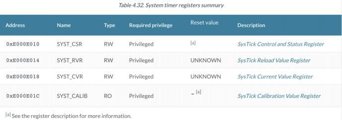
Please click each register’s hyperlink from table 4.32 to understand how the SysTick registers work.
For initialization in _timer_init,
(1) Make sure to stop SysTick:
Set SYST_CSR’s Bit 2 (CLK_SRC) = 1, Bit 1 (INT_EN) = 0, Bit 0 (ENABLE) = 0 (2) Load the maximum value to SYST_RVR:
The value should be 0x00FFFFFF which means MAX Value = 1/16MHz * 16M = 1 second
5.2. Signal
The signal( sig, *func ) function assumes only SIG_ALRM as the sig argument, while it accepts any address of *func (Keil C compiler automatically maps to memory). These sig and *funcarguments must be relayed from signal(sig, *func) all the way to _signal_handler in timer.s as keeping sig in R0 and *func in R1 respectively (based on APCS, see table 3). If R0 is SIG_ALRM, (i.e., 14), save it in memory address at 0x20007B84. Return the previous value of 0x2007B84 to main( ) through R0.
5.3. Alarm
The alarm( seconds ) function relays this seconds argument in R0 from main( ) all the way to _timer_start in timer.s. Retrieve the previous value at 0x20007B80 that is recognized as the previous time valuve and returned to main( ) through R0, save the new seconds value to 0x20007B80, and start the SysTick timer.
(1) Retrieve the seconds parameter from memory address 0x20007B80, which is the previous time value and should be returned to main( ).
(2) Save anew seconds parameter from alarm( ) to memory address 0x20007B80. (3) Enable SysTick:
Set SYST_CSR’s Bit 2 (CLK_SRC) = 1, Bit 1 (INT_EN) = 1, Bit 0 (ENABLE) = 1 (4) Clear SYST_CVR:
Set 0x00000000 in SYST_CVR.
5.4. SysTick Interrupt
A SysTick interrupt is caught at SysTick_Handler in startup_TM4C129.s. It is relayed to _timer_update in timer.s
This is the same as HW7-Q4.
The timer_update( ) function reads the value at address 0x20007B80, decrements the value by 1 (second), checks the value, branches to _timer_update_done if the value hasn’t reached 0, otherwise it needs to stop the timer and to invoke a user function whose address is maintained in 0x20007B84. To stop the timer, write “Bit 2 (CLK_SRC) = 1, Bit 1 (INT_EN) = 0, Bit 0 (ENABLE) = 0” to SYST_CSR. (Don’t forget to save back a decremented value into 0x20007B80.)
2024-02-18