Report for Experiment #11 Testing Newton’s Second Law
Hello, dear friend, you can consult us at any time if you have any questions, add WeChat: daixieit
Report for Experiment #11
Testing Newton’s Second Law
On the Moon
Abstract
In this experiment, we tested Newton’s second law and determined the acceleration due to gravity on the Moon. We used a frictionless air table equipped with a spark timer, and studied the motion of a puck
attached to a vertically hanging weight. In both setups that we tested, the puck’s acceleration changed linearly with the mass of hanging weight as expected from Newton’s second law, but in one case, the measured gmoon value was not consistent with the known value within the uncertainty.
Introduction
An object which is acted upon a non-zero total force undergoes an acceleration in the direction of the force. The relation between the acceleration of the object and the net force acting on it is given by
Newton’s second law [1], which can be expressed as

where  net is the net force, m is the object’s mass and
  denotes the object’s acceleration. As an example, for the case of free fall on Earth,
  net is equal to the object's weight and Newton’s second law reads

From this we can conclude that the object falls on Earth at a constant rate a = g = 9.81 m/S2 .
The goal of this experiment was to test Newton’s second law on the Moon by studying the motion of a puck attached to hanging weights on a frictionless air table, and to measure the acceleration due to
Moon’s gravity gmoon . In the first investigation, the motion of the puck pulled by three different weights was analyzed. The position of the puck was measured periodically, and the velocity and acceleration were determined. The accelerations were compared to the mass of the system to test Newton’s second law and to determine gmoon . The second investigation involved the same procedure, but the mass of the puck was doubled by adding extra weights to it. A similar analysis was performed and a second measured value of gmoon was obtained.
Investigation 1
The setup consists of pucks that float on a flat glass surface table using compressed air [2]. The motion of the pucks can be tracked from dots that are periodically marked by a spark timer on a white paper placed under the pucks. A sheet of carbon paper placed under the white paper provides the
electrical connection between the pucks and the spark timer. A pulley hooked up to the side of the table allows a puck to be attached to a vertically moving mass hanger.
Before data were collected, the air table was leveled by adjusting its three adjustable legs. The
spark timer was set to 10 Hz so that, when the circuit was closed by pressing the associated switch pedal, sparks were generated every 0. 1 S. The mass of the puck was measured to be mp = 550 g. For the first trial, a mass of mw = 200 g was used as the hanging weight.
Data were collected by pressing down the spark timer pedal and then releasing the puck. The
puck slid along the air table, generating sparks at fixed time intervals. When the puck reached the end of the table, the pedal was released and the white paper was removed and inspected. After skipping the first few dots, ten consecutive dots for which the puck was in a smooth motion were labeled 1-10. The
displacement between each set of three adjacent dots, Δx, was measured with a ruler and recorded.
Displacement #1, for example, was the distance between dots 1 and 3, while displacement #2 was the
distance between dots 2 and 4 (and so on). The instrumental uncertainty in these measurements, δΔx = 0.3 cm, was assessed based on the radius of the spark timer dots. The time interval between each pair of adjacent dots, Δt = 0. 1 S, was also noted. The relative uncertainty δΔt/Δt = 0.2% was provided by lab personnel. After these values were gathered and recorded for the 200 g trial, the process was repeated two more times with hanging masses of 400 and 800 g, respectively. The resulting data are provided in Table 1 below.
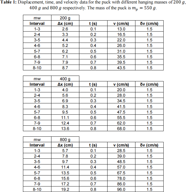
In order to determine the acceleration of the puck, the velocity had to be calculated from the raw displacement and time data at various points. Because each displacement Δx was defined over two time intervals Δt, the average velocity v during each displacement was calculated as:

The propagated uncertainties in these velocities, δv, are given by the relative uncertainties in time and displacement as:
The average velocities for each displacement interval were assumed to take place at the middle of each associated time interval. In other words, for the first v value, corresponding time was 0. 1 s, for the second one, t was 0.2 s and so on. The derived v, δv and t values are also included in Table 1.
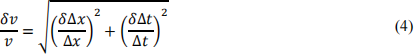
To calculate the acceleration, a plot of the average velocities vs. time plot was created (see Fig. 1 below). The data points were input into the IPL straight-line fit calculator [3] to determine the slopes, a, and their uncertainties, δa. The resulting values are provided in Table 2 below.
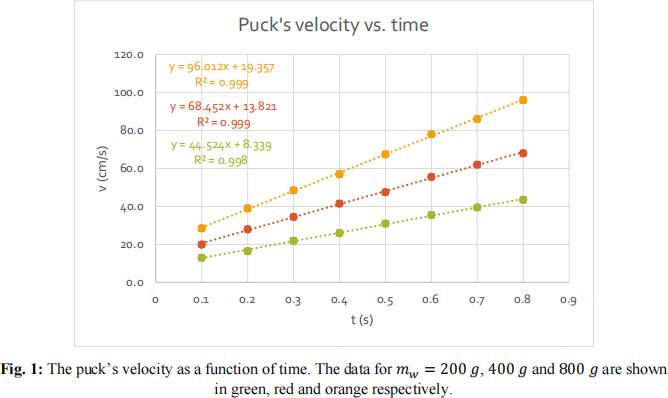
As previously discussed, Newton’s second law states that the sum of all forces on an object is equal to the product of its mass and acceleration. If we denote the mass of the hanging weight and puck as, respectively, mw and mp , then Eq. (1) can be used to describe the acceleration of the entire puck & hanging mass assembly, F = (mw + mp )a. The force on this assembly is just the gravitational force on the hanging mass, given by F = mw gmoon . The combination of these two equations gives:

where r = mw /(mw + mp) is the ratio of the attached mass to the total mass of the puck + attached weight system.
Thus there should be a linear relationship between the acceleration and the mass ratio r. In order to determine the acceleration due to gravity, the mass ratio was calculated for each trial (Table 2) and plotted as the independent variable against the acceleration (Fig. 2). Since the masses were measured very precisely, the errors in the mass ratios r were neglected. As expected from Newton’s second law, the data agrees well with a linear trend line and based on Eq. (6).
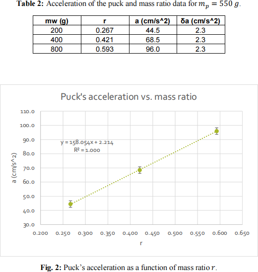
According to Eq. (5), the slope of this trend line is expected to be equal to gmoon . By inputting the data into the IPL calculator, the slope of the best fit line was determined to be 158 cm/s2. The uncertainty in the slope was 10 cm/s2 .Thus, the acceleration due to the Moon’s gravity was experimentally determined to be 1.58 ± 0. 10 m/s2 . The expected value, 1.62 m/s2 , falls within the range around the measured value defined by the measured value’s uncertainty, so Newton’s second law was verified.
Investigation 2
The second investigation consisted of the same setup as Investigation 1, except in this instance extra weight was added on the puck to double its mass to mp = 1100 g. The same procedure was used as before; the puck was attached to three different hanging masses and released. From the dots on the white paper, the displacements were measured and recorded in Table 3 below.
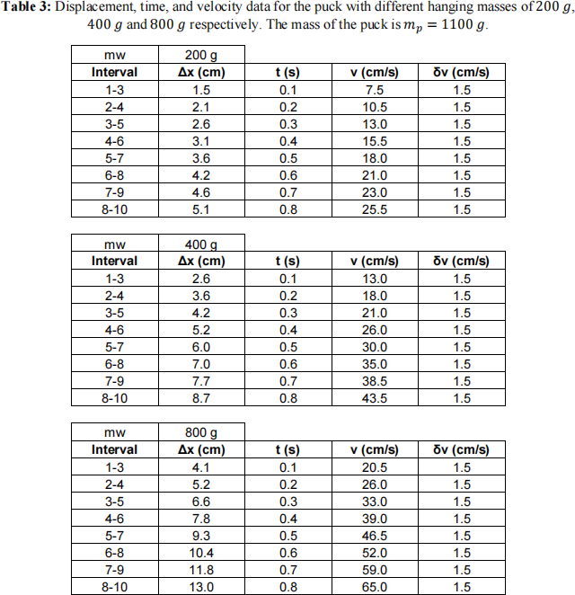
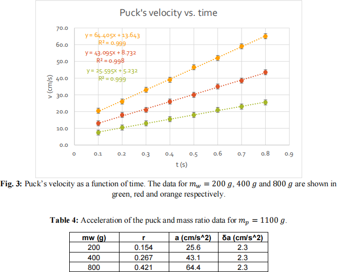
Once again, the average velocities and their uncertainties were calculated using Eqs. (3) and (4), respectively. The times at which these velocities took place were determined from the elapsed time at the central dot of each consecutive triplet. Velocity vs. time was graphed for each of the three weights used, as shown in Fig. 3.
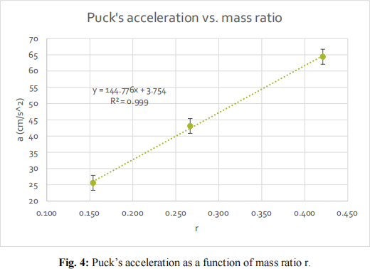
The accelerations for each case (and their uncertainties) were determined from the IPL straight-line fit calculator and are displayed in Table 4, along with their associated mass ratio. The accelerations of the pucks were again graphed against the mass ratio (Fig. 4) and error bars and a linear trend line were added.
Based on Eq. (6), the data were expected to once again linearly change with respect to mass
ratio r, and the slope of this plot was expected to be equal to the acceleration due to gravity. Although the linear trend line agreed very well with the data, the resulting slope value, 1.44 ± 0. 12 m/s2 , was not consistent with the expected value, 1.62 m/s2. As such, Newton’s second law was not corroborated by this investigation.
There might be many reasons for this slight disagreement. It is possible that with the added
weight, the puck was not able to float perfectly on the table but perhaps touched the paper underneath which created friction. The pulley could also affect the results by adding further friction. If present, this systematic error would have resulted in a force opposite the puck’s direction of motion, which would decrease the measured acceleration, which is what we observed.
Conclusion
This experiment consisted of two investigations, both of which attempted to test Newton’s second law and determine the gravitational acceleration on the Moon. An air table was used to create a frictionless surface and the motion of a puck attached to hanging masses was periodically marked by a spark timer. From these marks, the velocity of the puck at consecutive points in time was calculated. By plotting these velocities against the moments of times at which they occurred, the accelerations were determined. Using Newton’s second law, these accelerations were shown to be linearly related to the ratio of the attached weight to the total weight of the puck + weight system. By plotting these two quantities against each other, the linear relationship was tested and the acceleration due to Moon’s gravity was determined.
In both investigations, the acceleration data showed a linear trend with respect to the mass ratio as expected. In the first investigation, the gravitational acceleration was measured to be 1.58 ± 0. 10 m/s2 , which was consistent with the expected value of 1.62 m/s2 considering the stated uncertainty. However in the second investigation, the known value did not fall within the measured acceleration value
of 1.44 ± 0. 12 m/s2. It is possible that the air table did not create enough of an air cushion to
completely eliminate the effect of friction, which would lower the measured value. It is possible that the pulley used in the setup also added some friction.
In order to mitigate the effect of the unaccounted-for errors discussed above, further efforts could be made to reduce the friction present in the system. The air pressure could be increased to create a better air cushion and the pulley wheel could be better lubricated. To improve the precision of the results,
several changes to the procedure could be made. While the uncertainties in the time intervals were very small (and difficult to reduce further), the position measurements were significantly limited by the size of the spark timer dots. Thus, the precision with which the acceleration due to gravity is determined could be improved by decreasing δΔx. This could potentially be achieved by upgrading the spark timer or determining the center of the dots in a more precise manner.
Questions
Answers to the questions at the end of the lab.
Acknowledgements
I would like to thank my lab partner, Buzz Aldrin, for his assistance during the Moon landing,
and our TA, Michael Collins, for waiting to rendezvous with us in the Command Module orbiting around the Moon while we collected data on the Moon’s surface. Special thanks go to NASA for funding this
experiment.
References
[1] H. Young and R. Freedman, University Physics, p 111, Pearson Education, 14th edition.
[2] Hyde, Batishchev, and Altunkaynak, Introductory Physics Laboratory, pp 411-415, Hayden-McNeil, 2017.
[3] IPL Straight Line Fit Calculator, http://www.northeastern.edu/ipl/data-analysis/straight-line-fit/
2024-01-30