CENV3020 GEOTECHNICAL ENGINEERING SEMESTER 1 ASSESSMENT PAPER 2020/21
Hello, dear friend, you can consult us at any time if you have any questions, add WeChat: daixieit
SEMESTER 1 ASSESSMENT PAPER 2020/21
TITLE - CENV3020 GEOTECHNICAL ENGINEERING
Question 1
Figure Q1 shows a gravity wall retaining a body of sand. There is assumed to be no soil-wall friction at the interface between the soil and the wall.
(a). For the zone of soil behind the wall in Figure Q1, draw a Mohr’s circle at active failure and determine the angle from the horizontal at which the characteristic plane on which failure takes place will occur. Please show your working. [3 marks]
(b). By considering a wedge of soil sliding behind the wall, derive an expression for the minimum force that the wall needs to provide to the soil to maintain its stability. In solving the upper bound mechanism, use a work (force x velocity) solution. In your answer, show the hodograph that you use to resolve the velocity in the mechanism. [7 marks]
(c). Assuming that the critical mechanism follows the characteristic plane found in (a), use your solution to part (b) to find the horizontal force that the wall needs to provide to the soil to maintain its stability, when the soil properties are φ ’ = 30° and Y = 18 kN/m2, and the height of the wall is 2 m. [2 marks]
(d). If the soil-wall friction, δ , for the wall in Figure Q1 is now not equal to zero, explain qualitatively how that would change your answers to part (a) and part (b). [6 marks]
[Total Q1 = 18 marks]
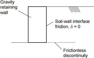
Figure Q1. Simple gravity wall and soil supported behind it.
Question 2
(a). Explain what happens to the total stress, effective stress, and pore water pressure in an element of clay soil as (i) a rapid excavation is made above it, and then (ii) as groundwater flow takes place towards equilibrium conditions. What is the effect of these changes on the stability of a wall retaining the excavation? [3 marks]
(b). The gravity wall shown in Figure Q2 has a sloping back face. Explain the potential advantages of having a sloping back to the wall. [2 marks]
(c). A gravity wall made up of pre-cast concrete elements is required as part of a road widening scheme. The proposed wall is shown in Figure Q2. By considering the limiting equilibrium of a series of potential active sliding wedges extending from the bottom corner of the wall, determine the minimum horizontal force that the wall would need to provide to maintain the stability of the soil behind it. Within your calculation, apply a factor of safety of 1.25 to tanφ’ . The soil and wall properties are given in Figure Q2. You may solve the problem either graphically by means of force vector diagrams, or algebraically by resolving forces. State clearly any assumptions that you need to make. [20 marks]
(d). Using your answer from part (c) above, draw a free body diagram of the wall with the appropriate forces acting on it. Using the free body diagram, determine the depth of wall D (where the dimension D is marked on Figure Q2) in order to maintain: (i) horizontal equilibrium of the wall; and (ii) moment equilibrium of the wall such that the soil stresses on the base remain compressive across the full width of the base of the wall. Apply a factor of safety of 1.25 to tanδ, where δ is the friction angle at the soil-wall interface. State clearly any assumptions that you need to make. [21 marks]

Figure Q2. Geometry and soil and wall properties for a gravity retaining wall used to widen a road.
(e). The pre-cast concrete wall in part (d) ends up being quite large, using significant quantity of concrete. Suggest three design changes that could be made that reduce its size. In each case, explain how the change would work. [6 marks]
(f). An alternative approach would be to form a wall from reinforced earth. Discuss qualitatively the key potential advantages and disadvantages of using both a wall made up of pre-cast concrete elements, and a wall made up of reinforced earth, for the arrangement described in Figure Q2. [6 marks]
[Total Q2 = 58 marks]
Question 3
Figure Q3 shows a simple steel mast used to support the overhead electrical power supply being added to an existing railway line, running on top of a clay embankment. The forces indicated are for one particular load case, with the horizontal force representing the extreme wind loading, and the vertical load the weight of the structure and a representative length of the supported power cables.
(a). Explain why a simple pad footing is unlikely to be a suitable form of foundation for the mast. [2 marks]
(b). It is decided to install the mast in Figure Q3 onto a foundation made up of a single driven circular hollow steel pile, of 0.6 m outside diameter. Determine the length of the pile required to carry the moment and horizontal loads acting on the structure. (For the time being, you should ignore the need for the pile to also carry a vertical load). Assume that where the pile is moving towards the slope, the limiting line load pu = 6τud, and where the pile moves away from the slope the limiting line load pu = 10.5τud (where d is the pile diameter), and that the limiting lateral resistance is zero for the first two pile diameters below the ground surface. The soil strength is given in Figure Q3; in your calculation you should apply a factor of safety of 1.4 to τu . State clearly any assumptions that you need to make. [14 marks]
(c). Now ignoring the horizontal and moment loads, calculate the length of pile required to carry the vertical load of 50 kN acting in isolation. Again, apply a factor of safety of 1.4 to τu, and assume that the pile-soil interface adhesion, τw = 0.5 ![]() τu. You should ignore the possibility that soil goes into the inside of the pile during driving. [2 marks]
τu. You should ignore the possibility that soil goes into the inside of the pile during driving. [2 marks]
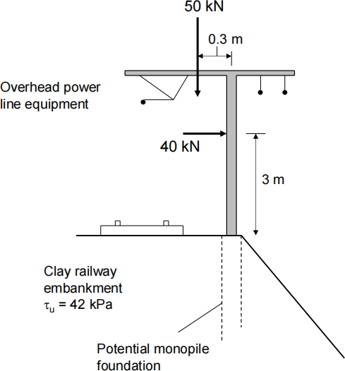
Figure Q3. Arrangement and loads acting on a steel mast carrying track catenary and power supply cables.
(d). The performance of the track catenary (the wire suspended above the track, and the ability of the train to stay connected with it) is dependent on a careful control of displacements of the mast and foundation. Discuss how you might go about determining the displacements of the mast and particularly its foundation under the applied wind loading. What additional information might you require? [6 marks]
[Total Q3 = 24 marks]
2024-01-20