GCG Vulkan Task Description Task 6
Hello, dear friend, you can consult us at any time if you have any questions, add WeChat: daixieit
GCG Vulkan Task Description
Task 6 (20 Points + 15)
(Document version: 2023.1)
+1 bonus point for choosing the Vulkan route!
Introduction
Real-life objects are usually not colored in a single color but exhibit a surface structure that can be represented using textures. It could be said that textures are images, which are "glued" to the surface of an object. This requires three steps:
1. The texture has to be loaded into GPU memory .
2. The texture should be mapped to objects in some meaningful way (which we are going to use UV coordinates for) .
3. During rendering, color values must be sampled from an appropriate location within the texture for each rendered fragment and used as the surface color with illumination computations .
UV coordinates are a general approach to attach a specific texture location to a vertex, and they can be implemented as additional vertex attributes (just like we have extended the vertex attributes during Task 3 and 5, when adding vertex color and normals) .
Additional Vertex Attributes: UV Coordinates
The objectives of the first three subtasks are to add UV coordinates as additional
vertex attributes to every geometric object .
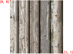
UV mapping is the task of computing a two-dimensional coordinate (which represents the corresponding location in a texture) for each vertex . This is a rather complex process for arbitrary shapes . Luckily, for primitive shapes there are some easier methods . To ensure a resolution-independent method, UV-coordinates are normalized to the range of 0 to 1, where (0, 0) in Vulkan corresponds to the top-left corner of the texture and (1, 1) corresponds to the bottom-right corner:
Note: You are free to choose how to store the different vertex attributes (positions, normals, and UV coordinates) . One option would be to store them in separate arrays/vectors, so that one array/vector contains all the positions (e.g ., p0, p1, p2, p3, . . . ), another array/vector contains all the normals (e.g ., n0, n1, n2, n3, . . . ), and yet another array/vector contains all the UV coordinates (e.g ., uv0, uv1, uv2, uv3, . . . ). A different option would be to put all vertex attributes into a common struct and store them in an interleaved manner (e.g ., p0, n0, uv0, p1, n1, uv1, p2, n2, uv2, p3, n3, uv3, . . . ) . In both cases, you'll have to provide the correct parameters for the stride members of the VkVertexInputBindingDescription instances . More detailed implementation instructions are described for Subtask 6.4.
Subtask 6.1: Add UV Coordinates to the Box Geometry
Your objective is to add UV coordinates to the box geometry, mapping the entirety of a texture to every face . Therefore, the top left vertex of a face shall be assigned the UV coordinate (0, 0) , and the bottom right vertex of a face shall be assigned the UV coordinate (1, 1) .
Subtask 6.2: Add UV Coordinates to the Cylinder Geometry
Your objective is to add UV coordinates to the cylinder geometry, mapping the entirety of a texture once to the lateral surface, and a circular region of a texture to top and bottom faces .
Starting with the lateral surface (side faces), the texture is wrapped around the
cylinder exactly once in its entirety . Hence, a top vertex always has a V coordinate of 0 ; and each bottom vertex has a V coordinate of 1 . The U coordinate only depends on the angle along the circle . Top and bottom faces of the cylinder are circular
shapes, but the texture is a rectangle (or square in terms of texture coordinates) .
For top and bottom faces, there are many possible ways to map a square to a circle, and any meaningful way is accepted here . The simplest approach is by simply cutting out a circle from the square texture . This is done by using the x and z positions
of a vertex and transforming it to the range [0, 1], where the transformed x corresponds to U, and the transformed z corresponds to V .
Note: The last segment of the lateral surface is distorted . This happens because the
UV coordinates are interpolated between the last and the first segment, jumping from
U=1 to U=0 . Since this problem doesn't have a trivial solution, it is fine to leave it
that way . Fixing this mapping problem can be done as a specialization task (see below) .
Subtask 6.3: Add UV Coordinates to the Sphere Gometry
Your objective is to add UV coordinates to the sphere geometry, mapping the entirety
of a texture once to the sphere's surface .
Spherical UV mapping can be established in a similar way as with the lateral surface
of a cylinder . The texture is wrapped around using horizontal and vertical angles to
compute UV coordinates . Note that the poles are distorted if only one vertex is used
because in such cases only one UV coordinate can be stored, whereas for every adjacent
vertex, a different U coordinate would be necessary . Similar to the cylinder, this
doesn't have to be fixed, but can be done as a specialization task (see below) .
Subtask 6.4: Add UV Coordinates to the Bézier Cylinder
Geometry
Your objective is to add UV coordinates to the Bézier cylinder geometry, mapping the
entirety of a texture once to the lateral surfaces, and a circular region of a texture
to top and bottom faces . Starting with the lateral surface (side faces), we measure
the distance between each sample point of the bezier curve to the previous one and add
it to the V coordinate or each vertex on the cirlce around it . The U coordinate is
calculated the same as you would also do it for the ordinary cylinder .
Subtask 6.5: Pass UV Coordinates As Vertex Attributes
During Subtask 3.4, you used vkCmdBindVertexBuffers to bind vertex position data as vertex attributes and you configured them to be streamed to the vertex shader's input location = 0 (as originally declared in the vertex shader during Subtask 2.1) .
During Subtask 6.6, you have added normals as additonal vertex attributes and bound
them to location = 1 so that they can be read and used in shaders . Now UV coordinates shall be added in the same manner .
Your objectives are:
![]() Add an additional vertex attribute input binding at location = 2 in the vertex shader, which shall receive the UV coordintes that are to be bound as additonal vertex attribute .
Add an additional vertex attribute input binding at location = 2 in the vertex shader, which shall receive the UV coordintes that are to be bound as additonal vertex attribute .
![]() Depending on your choice of data layout (separate arrays/vectors or interleaved data, as described above), you might have to add an entry to
Depending on your choice of data layout (separate arrays/vectors or interleaved data, as described above), you might have to add an entry to
V klGraphicsPipelineConfig::vertexInputBuffers (originally set-up during Subtask 2.1, then extended during Subtasks 3.7 and 5.6), describing the format of the
buffer(s) you are going to provide the API for reading vertex attributes from during draw calls . Make sure to read the documentation of
VkVertexInputBindingDescription carefully .
![]() Add an entry to V klGraphicsPipelineConfig::inputAttributeDescriptions
Add an entry to V klGraphicsPipelineConfig::inputAttributeDescriptions
describing where the UV coordintes data can be found! This description goes hand in hand with the data provided to
V klGraphicsPipelineConfig::vertexInputBuffers . Consult the documentation of VkVertexInputAttributeDescription and make sure to have normals streamed to input location = 2 !
![]() Possibly adapt the invocation of vkCmdBindVertexBuffers (as established during Subtask 3.4, and extended during Subtasks 3.7 and 5.6) to match the
Possibly adapt the invocation of vkCmdBindVertexBuffers (as established during Subtask 3.4, and extended during Subtasks 3.7 and 5.6) to match the
configuration provided to V klGraphicsPipelineConfig::vertexInputBuffers , and ensure that the draw call knows where to read the UV coordinates data from!
To test if UV coordinates have been successfully streamed to your vertex shader, you
could pass them on from the vertex shader:
layout (location = 0) out vec2 out_textureCoordinates;
to the fragment shader:
layout (location = 0) in vec2 in_textureCoordinates;
and write them to the fragment shader's output instead of writing color values as
required for the previous subtasks .
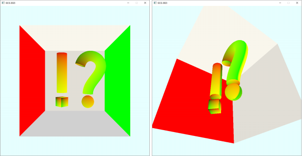
You should see the following output, when writing the U coordinate to the R channel, and the V coordinate to the G channel, leaving B at 0 :
Subtask 6.6: Interaction
Your objective is to use the functionality of Subtask 6.5 and implement user input to toggle the standard color view and texture coordinates view at run time! Extend the
key callback implemented during Subtask 1.11 and listen for an additional key [ T ]!
Similar to the previous settings, it should also be possible to set the rendering mode
by reading in a settings file specified in the command line arguments:
std::string init_renderer_filepath = "assets/settings/renderer_standard .ini";
if (cmdline_args .init_renderer) {
init_renderer_filepath = cmdline_args .init_renderer_filepath;
}
INIReader renderer_reader(init_renderer_filepath);
bool draw_texcoords = renderer_reader .GetBoolean("renderer", "texcoords", false);
To communicate this state to the shader, again use the ivec4 in your uniform buffer
created during Subtask 5.6.
When the user holds down key [T]:
![]() Write some value into your newly added ivec4 before the call to
Write some value into your newly added ivec4 before the call to
vklCopyDataIntoHostCoherentBuffer !
![]() Evaluate the user input in your fragment shader whether the magic value representing [ T ] is there .
Evaluate the user input in your fragment shader whether the magic value representing [ T ] is there .
![]() And if so, write texture coordinates to the fragment shader's color output!
And if so, write texture coordinates to the fragment shader's color output!
For example:
// In main.cpp
ub_data .userInput[1] = draw_texcoords ? 1 : 0;
// In your shader
if (ub_data .userInput[0] == 1) {
out_color = vec4(n, 1);
}
if (ub_data .userInput[1] == 1) {
out_color = vec4(frag_in .textureCoordinates, 0, 1);
}
Subtask 6.7: Load DDS Textures into Images
First of all, textures need to be loaded from files. Along with the provided
framework, several DDS image files have been distributed . The framework provides the function vklLoadDdsImageIntoHostCoherentBuffer to load a DDS texture from file into a host-coherent buffer .
Important: Please always use relative paths when loading files, otherwise the program
won't run on a different computer (which is necessary for the submission talks) .
Hint: Similar to shader file handling, you are expected to place textures in the
directory assets/textures/ relative to the project root (where the CMakeLists .txt is located). A proper path passed to vklLoadDdsImageIntoHostCoherentBuffer would look,
e.g ., like follows: "assets/textures/wood_texture .dds" .
The function vklLoadDdsImageIntoHostCoherentBuffer loads (as its name indicates) the texture data from file into a host-coherent buffer . Host-coherent buffers require
their data to be stored in a certain memory region which allows them to be written
from the host-side directly . While this is very convenient for many use cases, it
often means (depending on the device used) that performance is sacrificed when that
memory is accessed on the device-side (i.e ., from your GPU during rendering) . There
are usually memory regions which can be accessed much faster by the device, and we're going to use such faster memory regions when creating images . The downside of these
faster "device-only" memory regions is that they cannot be accessed directly from the host-side . Therefore, we need an additional step to transfer data from host-coherent memory into device-only memory .
Your objectives are:
![]() Load a DDS texture from file into a host-coherent VkBuffer using the framework function vklLoadDdsImageIntoHostCoherentBuffer !
Load a DDS texture from file into a host-coherent VkBuffer using the framework function vklLoadDdsImageIntoHostCoherentBuffer !
![]() Create a VkImage that has its associated data stored in device-only memory via the framework function vklCreateDeviceLocalImageWithBackingMemory !
Create a VkImage that has its associated data stored in device-only memory via the framework function vklCreateDeviceLocalImageWithBackingMemory !
![]() Pass appropriate values for its width , height , and format parameters which you can get via vklGetDdsImageInfo !
Pass appropriate values for its width , height , and format parameters which you can get via vklGetDdsImageInfo !
![]() Pass appropriate image usage flags to its VkImageUsageFlags parameter which allow the image to be used a) as the destination of a transfer
Pass appropriate image usage flags to its VkImageUsageFlags parameter which allow the image to be used a) as the destination of a transfer
command, and b) also to be sampled by a shader! You'll find the
appropriate flags in the specification for VkImageUsageFlagBits .
![]() Create a VkCommandPool via vkCreateCommandPool ! Hint: You only need one command pool overall, do not create a new one per texture!
Create a VkCommandPool via vkCreateCommandPool ! Hint: You only need one command pool overall, do not create a new one per texture!
![]() Allocate a VkCommandBuffer from the command pool using
Allocate a VkCommandBuffer from the command pool using
vkAllocateCommandBuffers and record the following instructions into it:
1. Begin recording using vkBeginCommandBuffer !
2. Record an image layout transition on the created VkImage via
vkCmdPipelineBarrier which transitions from VK_IMAGE_LAYOUT_UNDEFINED to VK_IMAGE_LAYOUT_TRANSFER_DST_OPTIMAL ! Hint: You'll need to use an
instance of VkImageMemoryBarrier with vkCmdPipelineBarrier for that purpose .
3. Copy the contents of the VkBuffer into the VkImage using
vkCmdCopyBufferToImage! Hint: Regarding the destination image, copy to mipmap level 0 , and also to array layer 0 ! There is only one mipmap
level and only one array layer to copy from the buffer into the image .
(Therefore, also the image layout transitions only need to be applied to that subresource range.)
4. Record another image layout transition on the VkImage via
vkCmdPipelineBarrier which transitions from
VK_IMAGE_LAYOUT_TRANSFER_DST_OPTIMAL to
VK_IMAGE_LAYOUT_SHADER_READ_ONLY_OPTIMAL to enable the image to be accessed from shaders!
5. End recording using vkEndCommandBuffer !
![]() Create a VkFence via vkCreateFence and ensure that it is not created in the signaled state, but instead, unsignaled!
Create a VkFence via vkCreateFence and ensure that it is not created in the signaled state, but instead, unsignaled!
![]() Submit the recorded VkCommandBuffer to the queue which you have retrieved
Submit the recorded VkCommandBuffer to the queue which you have retrieved
during Subtask 1.7 and also pass the VkFence so that it gets signaled after he commands in the command buffer have completed execution!
![]() Use vkWaitForFences to wait on the fence being signaled before the next usage of the VkImage , ensuring that it contains the texture's data .
Use vkWaitForFences to wait on the fence being signaled before the next usage of the VkImage , ensuring that it contains the texture's data .
![]() Ensure to cleanup the VkFence , the VkCommandBuffer , the VkBuffer , and the VkImage when you no longer need them!
Ensure to cleanup the VkFence , the VkCommandBuffer , the VkBuffer , and the VkImage when you no longer need them!
![]() Use the implemented functionality to load two DDS textures: wood_texture .dds and tiles_diffuse .dds !
Use the implemented functionality to load two DDS textures: wood_texture .dds and tiles_diffuse .dds !
Optional: Use Synchronization2
You can think about using "VK_KHR_synchronization2" , which has the advantage that the pipeline barriers which are required to perform the image layout transitions are
specified in a clearer and more logical manner .
To enable Synchronization2 in your application, first enable the device extension "VK_KHR_synchronization2" !
After VkDevice creation and if enabling "VK_KHR_synchronization2" was successful, you'll have to get the function pointer for vkCmdPipelineBarrier2KHR , which is the appropriate function to record a pipeline barrier with Synchronization2 and is to be used instead of vkCmdPipelineBarrier . Because it is an extension, the function
pointers are not loaded by default but have to be loaded manually . Proceed as follows:
1. Declare a global variable
PFN_vkCmdPipelineBarrier2KHR g_vkCmdPipelineBarrier2KHR;
2. Get vkCmdPipelineBarrier2KHR 's function pointer as follows:
auto* procAddr = vkGetDeviceProcAddr(vk_device, "vkCmdPipelineBarrier2KHR");
if (procAddr == nullptr) {
// Couldn 't get the function pointer to vkCmdPipelineBarrier2KHR
}
else {
g_vkCmdPipelineBarrier2KHR = reinterpret_cast<PFN_vkCmdPipelineBarrier2KHR>
(procAddr);
}
3. If successful, use the function pointer stored in g_vkCmdPipelineBarrier2KHR just like you would use vkCmdPipelineBarrier2KHR ! I.e ., like follows:
g_vkCmdPipelineBarrier2KHR(my_command_buffer, &my_dependency_info);
Furthermore, ensure to use the enum values from
![]() VkPipelineStageFlagBits2KHR instead of VkPipelineStageFlagBits , and
VkPipelineStageFlagBits2KHR instead of VkPipelineStageFlagBits , and
![]() VkAccessFlagBits2KHR instead of VkAccessFlagBits !
VkAccessFlagBits2KHR instead of VkAccessFlagBits !
Subtask 6.8: Create an Image View for each Image
Your objective is to create a VkImageView for each one of the VkImage handles created during Subtask 6.6 via vkCreateImageView !
There is no need to change the format nor to change the component mappings . You can leave the baseMipLevel = 0 , the levelCount = 1 , the baseArrayLayer = 0 , and the layerCount = 1 for now; but keep in mind that some of these values will have to be changed according to the requirements of Subtasks 5.10 and 5.13!
Subtask 6.9: Create a Sampler
Your objective is to create a VkSampler via vkCreateSampler which uses linear filtering for minification, magnification, and also for the mipmap lookups! Set minLod = 0 .0f and maxLod = VK_LOD_CLAMP_NONE (in preparation for Subtask 6.11)!
Subtask 6.10: Use the Textures in Shaders
Your objective is to create a descriptor of descriptor type
VK_DESCRIPTOR_TYPE_COMBINED_IMAGE_SAMPLER per texture and pass it to shaders . For creating this type of descriptor, you've got to combine a VkImageView handle from Subtask 6.7 with the VkSampler from Subtask 6.8. While you'll require different
VkImageView handles to represent different textures, you can re-use the VkSampler for all the different descriptors .
Furthermore, your objective is to access sampled textures in shaders through a suitable binding location! Use the GLSL function texture together with the UV
coordinates passed during Subtask 6.5 to read color values from the textures! Instead
of using constant color values for the diffuse surface color of an object (as in all
previous tasks so far), now use the color from the texture as an object's diffuse
surface color!
A VK_DESCRIPTOR_TYPE_COMBINED_IMAGE_SAMPLER descriptor can be used in GLSL shaders like follows:
layout (binding = 3) uniform sampler2D diffuse_texture;
// ...
vec2 uv; // TODO: Assign!
vec3 diffuseColor = texture(diffuse_texture, uv) .rgb;
Note: It is sufficient to only extend the Phong-Phong shader!
Hint 1: Do not forget to extend the descriptor pool's size! In particular, make sure to add VkDescriptorPoolSize entries for the newly introduced
VK_DESCRIPTOR_TYPE_COMBINED_IMAGE_SAMPLER -type descriptors! Allocate space for at least three of these new descriptors, but still watch out for
VK_ERROR_OUT_OF_POOL_MEMORY errors . Different GPU vendors appear to interpret the sizes differently. While one GPU vendor might size the pool according to
VkDescriptorPoolSize::descriptorCount * VkDescriptorPoolCreateInfo::maxSets , other
vendors might disregard the maxSets parameter and base the total pool size solely on
VkDescriptorPoolSize::descriptorCount . Request an even greater pool size for the specialization tasks!
Hint 2: Do not forget to add the additional descriptors to the descriptor layout when
creating pipelines (see VklGraphicsPipelineConfig::descriptorLayout )!
Hint 3: Do not forget to add additional VkWriteDescriptorSet entries when writing data into the descriptor sets!
2024-01-16