CIVE5975 Foundation Engineering Example Exam Questions – Section B
Hello, dear friend, you can consult us at any time if you have any questions, add WeChat: daixieit
CIVE5975 Foundation Engineering
Example Exam Questions - Section B
These questions are designed to examine your understanding of foundation engineering. On average, it should take you thirty five to forty five minutes to complete each question. This is feasible provided you have studied the subject in advance.
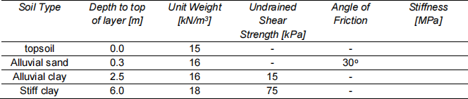
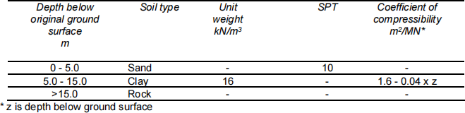
1. The feasibility of installing a wastewater tank, 4m deep, 30m long and 15m wide (internal dimensions) with four internal walls perpendicular to the long axis of the tank, in an alluvial flood plain is being considered. The level site is adjacent to a river subject to a tidal range of 2m and a mean water level of 2m below the site level. The site is known to frequently flood. The soil profile is given in Table 1- 1.
Preliminary structural calculations suggest that the internal and external walls will be 0.2m thick reinforced concrete; and the floor will be 0.3m thick reinforced concrete. The exterior walls will be cast in situ walls and propped by internal walls and the floor slab.
a. Consider the hazards associated with this site and structure and identify the most critical condition.
b. Set out your assumptions and produce a set of calculations to show that the proposed design is acceptable or unacceptable.
Table 1- 1 Soil profile and properties
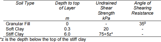
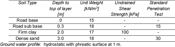
2. A retail park formed of lightweight single story structures is to be created in an alluvial plain which is known to be underlain by up to 10m of soft clay. In order to complete a feasibility study, assume each building will be 100m by 50m with a total contact pressure of 20kPa at 0.5m below ground level. The ground investigation provided the details in Table 2- 1.
Assess whether the total and differential settlement will be acceptable.
Table 2- 1 Soil profile and properties
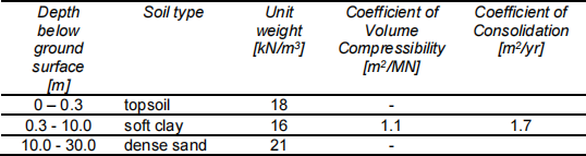
Ground water profile: hydrostatic with phreatic surface at 1m.
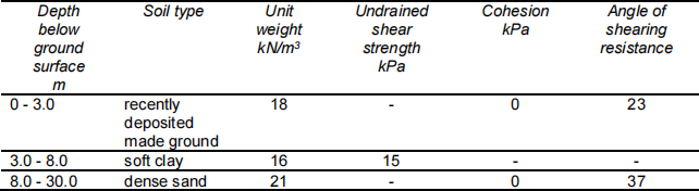
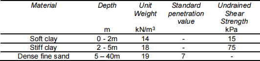
3. A 4m diameter monopile is 20m long. It has to be installed at the sea bed through 4m of alluvial clay into dense sand. The method of installation is to lower the pile onto the sea bed, evacuate the pile and use the pressure of the sea water to force the pile into the sea bed. Calculate the minimum depth of seawater needed to install the pile. [Hint: you must consider the possible forces acting on the pile during installation.]
The alluvial clay has a unit weight of 15kN/m3 and an undrained shear strength of 15kPa; the average blow count in the dense sand is 20.
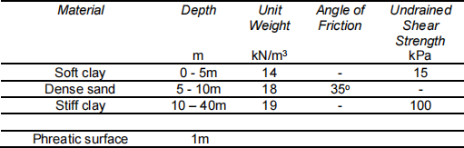
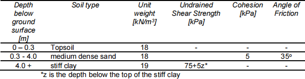
4. Calculate the effect lowering the groundwater table from 1 m to 5 m below the ground surface has upon the safe capacity of a block of concrete which acts as a machine foundation. The block, the top of which is 2m above the ground surface, is 3 m deep, 10 m long and 4 mwide. It carries a load of 600 tonnes.
Use a global factor of safety to assess the safe capacity. The soil profile consists of a medium dense sand of unit weight 21 kN/m3 , cohesion 3 kPa and angle of shearing resistance 35o.
Describe what would happen to the level of the foundation if the ground water level was rising from 5 m below ground level to ground level.
5. A 500 mm diameter reinforced concrete cfa pile is 25m long. The soil profile consists of clay which has a unit weight of 20kN/m3. The undrained shear strength to vertical effective stress ratio is 0.8 with the ground water level at 1.5m below the ground surface. Calculate the capacity of the pile using partial factors if a surcharge of 10kPa is applied to the ground surface.
Based on the calculated capacity determine whether some means of reducing the effect of the negative friction should be developed and, if so, what should that be.
6. A 0.6m diameter cfa compression pile is 20m long and has been bored through 4m of loose sand (N = 8) into dense sand (N = 15). The groundwater profile is hydrostatic with the water table at 2m below the ground level. It is proposed to carry out a load test using four tension piles as reaction. Estimate the maximum capacity of the compression pile and use that to design the length of 300mm diameter cfa tension piles.
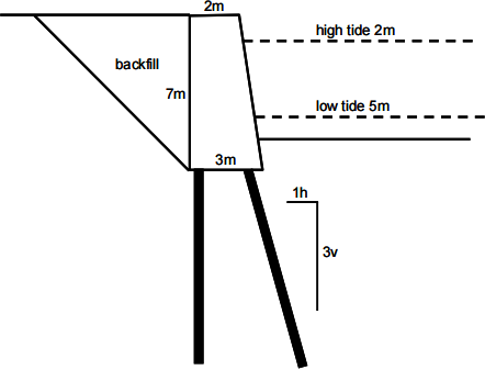
7. The figure shows a quay wall alongside a river, built in the 19th century that is showing signs of distress. Draw sections showing possible failure mechanisms and estimate the worst possible force on the vertical pile assuming that the vertical piles are three metres apart.
The unit weight of the backfill above the water ground water level is 16kN/m3 ; the unit weight below the groundwater level is 21kN/m3. The angle of friction of the backfill is 35o ; there is no cohesion. High water is 2m below the top of the wall; low water is 5m below the top of the wall. Assume the horizontal soil pressure on the wall at depth z below the top of the wall is 0.27σv’ .
The ground water level and river level are at the same level at all tidal conditions. The unit weight of the wall above the water level is 24kN/m3 .
8. Calculate the minimum and maximum axial compressive capacity of a 1.2 m diameter closed- ended steel tube pile driven 20 m into the soil profile given in Table 8- 1.
Table 8- 1 Soil profile and properties
Ground water profile: hydrostatic with phreatic surface at 3 m.
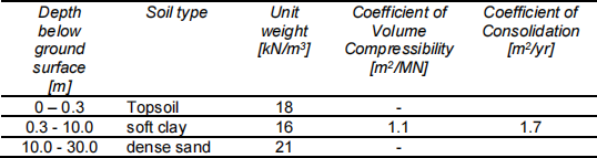
9. It is proposed to raise the general level of a site by 3m using imported, compacted fill (unit weight of fill = 15 kN/m3). Calculate the likely short and long term settlement for the ground profile given in Table 9- 1.
If the fill settles, extra fill will have to be brought in to raise the ground to the required level. How much fill is required if the site is 150 m by 150 m and what additional settlement will it cause?
Table 9- 1 Soil profile and properties
* z is depth below ground surface
10. A group of piles are to be driven through soft clay into a stiff clay underlain by a dense sand. The soil data are given in Table 10- 1. The pile group has to carry 4500T. The contractor has, in stock, solid concrete 500mm diameter piles. The 15m square pile cap will be cast onto a drainage blanket of granular material 300mm thick.
Determine the most economic number of piles required to produce a safe, stable structure if the effects of group interaction mean that each pile carries 75% of its capacity if it was a single pile.
Table 10- 1 Soil Data
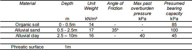
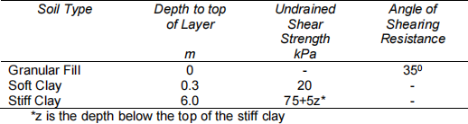
11. A ground investigation for a mixed development provided the information in Table 11- 1. The mixed development includes two storey houses, which have atypical load at foundation level of 80kN/m; and four storey town houses, which have a foundation load of 200kN/m.
Using the data provide develop a case for appropriate foundations.
a. List the key points you need to consider.
b. Using typical dimensions for shallow foundations assess whether bearing failure will occur.
c. Assess whether settlements are likely to be excessive.
d. Provide an overview of possible foundation solutions for the two storey and four storey houses.
Table 11- 1 Soil characteristics
12. The feasibility of installing a wastewater tank, 4m deep, 30m long and 15m wide (internal dimensions) with four internal walls perpendicular to the long axis of the tank, in an alluvial flood plain is being considered. The level site is adjacent to a river subject to a tidal range of 2m and a mean water level of 2m below the site level. The site is known to frequently flood. The soil profile is given in Table 12- 1.
Preliminary structural calculations suggest that the internal and external walls will be 0.2m thick reinforced concrete; and the floor will be 0.3m thick reinforced concrete. The exterior walls will be cast in situ walls and propped by internal walls and the floor slab.
a. Consider the hazards associated with this site and structure, and identify the most critical condition.
b. Set out your assumptions and produce a set of calculations to show that the proposed design is acceptable or unacceptable.
Table 12- 1 Soil profile and properties
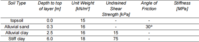
13. A retail park formed of lightweight single story structures is to be created in an alluvial plain which is known to be underlain by up to 10m of soft clay. In order to complete a feasibility study, assume each building will be 100m by 50m with a total contact pressure of 20kPa at 0.5m below ground level. The ground investigation provided the details in Table 13- 1.
Assess whether the total and differential settlement will be acceptable.
Briefly explain the principles of methods that could be used to reduce differential and total settlement?
Table 13- 1 Soil profile and properties
Ground water profile: hydrostatic with phreatic surface at 1 m.
14. A group of piles are to be driven through soft clay into a stiff clay underlain by a dense sand. The soil data are given in Table 14- 1. The pile group has to carry 4500T. The contractor has, in stock, solid concrete 500mm diameter piles. The 15m square pile cap will be castonto a drainage blanket of granular material 300mm thick.
Determine the most economic number of piles required to produce a safe, stable structure if the effects of group interaction mean that each pile carries 75% of its capacity if it was a single pile.
Table 14- 1 Soil Data
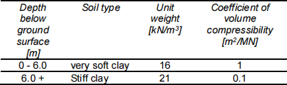
15. When constructing basements in London in stiff clay, account has to be taken of the swelling pressures acting on the floor slab. The building is likely to be supported on deep foundations with the floor slab spanning between the columns. If the floor slab is placed on the base of the excavation, then it is necessary to design the slab for the swelling pressures.
A new building will have a 10m deep basement. The floor slab will span 20m both ways between columns. Assuming a simple model of a square slab, estimate the maximum amount of swelling acting on the slab assuming the soil is over consolidated.
The soil profile is a firm to stiff clay which has a unit weight of 18kN/m3. The coefficient of volume compressibility is 0.05m2/MN. The groundwater level is at 2m below ground level.
16. It is proposed to support a 3m high embankment on piles in the soils with the properties shown in Table 16- 1. It is proposed to use 0.5m diameter cfa piles 2.5m apart. Calculate the minimum length of piles using Eurocode Design Method 1, Combination 1.
Table B16- 1 Soil profile and properties
17. It is proposed to construct a 1m diameter tunnel beneath a road next to which sits a four storey Victorian brick building which is built on 1m wide shallow foundations 1m deep. The load on the foundations is 200kN/m which are 30m long parallel to the road. The axis of the tunnel is 2m below the ground surface and 2m from the edge of the foundations. Calculate the maximum pressure acting on the crown of the tunnel.
During tunnel construction, diagonal cracks were noticed in the Victorian building. The owners of the buildings were concerned so all work on the tunnel stopped. Explain why the building could have cracked and put forward a proposal to prevent further movement of the building yet still the tunnel to be completed using the information in Table B17- 1. Calculations are not necessary.
Table B17- 1 Soil profile and properties
18. A caisson is being used to construct a bridge pier 5m of water. It is sunk through very soft clay 3m into a stiff clay with properties given in Table B18- 1.The caisson is 15m in diameter (external) and formed of 0.75m thick reinforced concrete units. The base of the caisson after it is installed is a 3m thick reinforced concrete raft integral with the walls of the caisson. The raft is designed to carry a permanent load of 5000T. Assume the top of the caisson is always at least 1m above water level. Estimate the settlement of the caisson.
Table B18- 1 Soil profile and properties
19. A group of piles consists of nine 0.3m diameter cfa piles spaced at 1m centres to form a square grid shown in Figure B19- 1. The pile cap supports a design vertical load of 100T. Determine which piles carries the maximum load and calculate that load.
The piles are driven through 4m of medium dense sand into a stiff clay (properties given in Table B19- 1). Determine the maximum length of the piles if the global factor of safety is 3.
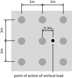
Figure B19- 1 Pile layout showing line of action of design load
Table B19- 1 Soil profile and properties
Ground water profile: hydrostatic with phreatic surface at 1 m.
20. A piled raft is 21m long and 15m wide. The 0.4m diameter cfa piles are drilled through 5m of medium dense medium sand into stiff clay. The piles are at 1.5m centres and the formation level of the pile cap is 0.75m below ground level. Calculate the minimum length of pile using Design Approach 1 Combination 2 and the soil properties given in Table B20- 1. The load on the raft is 3000T.
Table B20- 1 Soil profile and properties

Ground water profile: hydrostatic with phreatic surface at 1 m.
21. Determine the depth to ensure the ultimate limit state is satisfied for a rectangular, shallow
foundation 10m long by 5m wide carrying a load of 500T using Design Method 1, Combination 1. The soil profile is given in Table B21- 1.
Table B21- 1 Soil profile and properties
Ground water profile: hydrostatic with phreatic surface at 1.5 m.
2024-01-16