EEEN60631 Analysis of Electrical Power and Energy Conversion Systems
Hello, dear friend, you can consult us at any time if you have any questions, add WeChat: daixieit
EEEN60631
Faculty of Science and Engineering
School of Engineering
Department of Electrical and Electronic Engineering
Analysis of Electrical Power and Energy Conversion Systems
Question 1
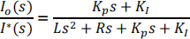
(a) A power electronics interface in a DC distribution system has the circuit shown in Figure Q1.1. The current iO(t) is controlled with a PI controller.

Figure Q1.1
(i) Draw the state-feedback system-block (SFSB) diagram of the system clearly labelling each block.
(ii) From first principles, derive the input-output control transfer function and show that this is equal to:
State all assumptions used. Symbols have their usual meanings.
(iii) The converter has inductance and resistance of 1.73 mH and 249 mΩ respectively. The system tuning is approximated to second order. If the values KP = 2.8 Ω and KI = 7600 Ω/s are programmed into the controller, what are the natural frequency and damping ratio of the response?
(iv) A digital microcontroller is designed to implement the PI controller in part (iii). The designers use the Tustin approximation with a 0.25 ms sampling frequency and the controller is programmed using the format

where the symbols have their usual meanings. Calculate a and b. [5, 8, 4, 4 marks]
(b) The circuit in Figure Q1.1 is to be modelled by two engineers. One will investigate the semiconductor design including losses. The other will investigate the control interaction of the converter with the rest of the DC system. Describe the level of modelling fidelity that each should use and justify your answer. [4 marks]
Total [25 marks]
Question 2
(a) A three-phase inverter is controlled using dq current feedback control. The control State-Feedback System Block diagram is shown in Figure Q2.1. For the inverter, L= 1.12 mH, and R = 9.1 mΩ. Kp = 3.3 Ω and Ki = 4900 Ω/s. You may assume that d- and q-axis controls have been decoupled and are independent.

Figure Q2.1
(i) Sketch the Dynamic Stiffness (DS) log magnitude vs. log frequency plot for this system, labelling the asymptotes.
(ii) Calculate the approximate frequency break-points as the DS plot changes from one asymptote to another.
(iii) At a particular operating point, a 40 V peak network disturbance voltage (Vnetwork) occurs at 6.05 kHz due to a sinusoidal voltage harmonic. Sketch the d-axis current variation resulting from this voltage, labelling the current waveform period and amplitude.
(iv) At another operating point, different from part (iii), current harmonics occur with magnitudes of 0.3 A at 2.9 kHz, 0.8 A at 3 kHz, 0.3 A at 3.1 kHz, 0.4 A at 5.95 kHz and 0.4 at 6.05 kHz. If the 50 Hz current is 7.1 A, what is the total harmonic current distortion percentage? (All values are phase peak amplitudes).
(v) Draw the amplitude of the Bode plot (loop-gain) of the system. [3, 4, 9, 2, 7 marks]
Total [25 marks]
Question 3
(a) An AC tie line connects two areas of a power system that operates with a nominal frequency of 60 Hz. Both areas operate with droop-based frequency control and no automatic generation control strategy is used.
The data relating to the frequency behaviour of both systems are given in Table Q3.1. All symbols in Table Q3.1 have their standard meanings.
Table Q3.1

The system is operating in steady state with 180 MW flowing from Area 2 to Area 1 when a 300 MW load in Area 1 is suddenly disconnected.
Determine the new steady state frequency in Hz. [4 marks]
(b) A 50 Hz synchronous power system operates with primary frequency control, and no secondary control (i.e., no Automatic Generation Control). All generators in the system have a primary frequency control droop constant of 4%. A generator outputting 650 MW is suddenly disconnected and the frequency stabilises at a new steady state value of 49.75 Hz.
The system operator changes all the droop constants so that they are now equal to 5%. The system is operating at its nominal frequency again. If the same generator outputting 650 MW is disconnected again, would the settling frequency be higher or lower than 49.75 Hz? Explain your reasoning with reference to an appropriate equation. [2 marks]
(c) Consider a power system, which consists of two areas (Area 1 and Area 2). Area 1 is connected to Area 2 by a 50 km long cable. During the day, there is high power transfer through the cable from Area 2 to Area 1. Overnight, when loading is reduced, the power flow through the cable reduces significantly. The power system operator is experiencing difficulties due to excessively high voltages on the cable overnight.
Explain the cause of the high voltages and choose one item of equipment that the power system operator should install to improve network performance. Explain why your selection is appropriate for the conditions described. [5 marks]
(d) A small power system is shown in Figure Q3.1 including generator and transformer winding connection details. All parameters for this system are given in Table Q3.2. All shunt susceptances are neglected. This system experiences a single line to ground fault at a point F on the line L1. The point F is at a distance d = 14.5 km from Bus 4 along the line L1. The total length l of the line L1 is 50 km. Note that the location of d is not drawn to scale in Figure Q3.1. Assume that the system is unloaded and operating at its nominal voltage.
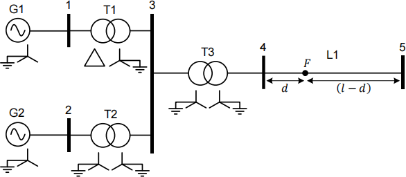
Figure Q3.1
Table Q3.2

Determine the fault current that flows at the fault point F in amps. [11 marks]
(e) A power system engineer is performing a symmetrical fault calculation by hand using a common system base of 1000 MVA. An external grid with a short circuit fault level of 2852 MVA is included in the calculation. The external grid has an X:R ratio of 12:1. The external grid will be represented using a Thevenin equivalent circuit with a voltage source of 1.0 p.u. and a series impedance. Determine the equivalent per unit impedance that should be used to represent the external grid. [3 marks]
Total [25 marks]
Question 4
(a) A power flow problem is being solved using the Newton Raphson approach on a power system model that contains 350 buses. All synchronous generators within the network are equipped with voltage control. Any bus without a generator is a
load bus. The network contains no on-load tap-changers. A single slack bus is
used in the solution. The Jacobian matrix used to determine the solution has
619 rows. Answer the following questions:
(i) How many load buses are there?
(ii) How many implicit equations will be formed?
(iii) How many rows are there in the  block in the Jacobian matrix?
(iv) How many PV buses are there? [1, 1, 1, 1 mark]
Eight new generators are added to the system at buses that were previously considered to be load buses. The generators are equipped with voltage control. Following this change to the power system model, the dimensions of the Jacobian change. Answer the following questions:
(v) How many implicit equations will be formed?
(vi) How many rows are there in the  block in the Jacobian? [1, 1 mark]
(b) A five-bus power system is shown in Figure Q4.1. It contains two generators (G1 and G2), two lines (Line 1-3 and Line 2-3), and two transformers (T1 and T2). Loads are connected at buses 3, 4, and 5. Transformer T1 has an on-load tap changer (OLTC) with a variable off-nominal turns ratio 1: t and the secondary winding is connected at bus 4. A power flow problem is to be formulated for the system. G1 is the slack bus for the system. G2 regulates the voltage at bus 2 to 1.05 p.u. and injects 40 MW into the network. Line 1-3 has a reactance of 0.20 p.u. and Line 2-3 has a reactance of 0.40 p.u. Line resistance and susceptance is neglected. Both T1 and T2 have impedances of j0.25 p.u. All per unit values are given on a 100 MVA base.
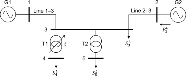
Figure Q4.1
(i) Formulate the Y-bus matrix for the network. Some matrix elements should include the parameter t.
(ii) The OLTC controls the voltage magnitude at bus 4 to 1.0 p.u. Write the algebraic form of the Jacobian matrix that will be used to find the solution when the values of  are all known. You should use the algebraic partial derivative terms for the implicit mismatch equations and the unknown variables. For example, the term
  could be used for this purpose. (Note that this term is just an illustrative example and may not actually appear in your answer). [3, 2 marks]
(c) A four-bus power system is shown in Figure Q4.2. An external grid at Bus 1 regulates the voltage magnitude at Bus 1 to 1.0 p.u. The network contains a generator at Bus 3 that delivers a constant 120 MW to the network and regulates the voltage magnitude at Bus 3 to 1.0 p.u. The loads at Bus 2, Bus 3 and Bus 4 are 50 MW, 100 MW, and 150 MW respectively. All loads have lagging power factors of 0.98. All lines have the same per-km impedance of 0.002 + j0.02 p.u./km on a 50 MVA base. Line susceptance is neglected. Line 1 is 10 km, Line 2 is 5 km, Line 3 is 15 km, Line 4 is 12 km, and Line 5 is 10 km.
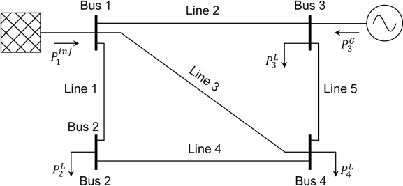
Figure Q4.2
(i) Using the DC power flow method, determine the active power flowing through Line 1 in MW. [9 marks]
(ii) Line 3 is now disconnected from the system. Again, using the DC power flow method, determine the active power flowing through Line 1 in MW. [5 marks]
Total [25 marks]
2024-01-11