MKEP 1603 – FINAL EXAMINATION
Hello, dear friend, you can consult us at any time if you have any questions, add WeChat: daixieit
MKEP 1603 – FINAL EXAMINATION
Q.1
(a) (i) Define the load flow analysis (LFA). (3 marks)
(ii) Give 2 (two) purposes of LFA in power system design and operation. (2 marks)
(b) Figure Q.1 (b) shows a three-bus power system with per unit line admittance. The Ybus matrix for the system is given by:
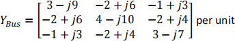
Bus 1 is a slack bus and is set at V1 = 1.06∠0° pu. Bus 2 and Bus 3 are P-Q buses. The per unit power system data at Bus 2 and Bus 3 are specified in Figure Q.1 (b).
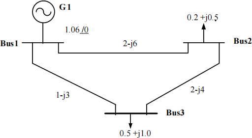
Figure Q.1 (b)
Referring to the system given in Figure Q.1 (b), by applying Fast Decoupled method: -
(i) Compute the voltage at all buses at the end of first iteration. (13 marks)
(ii) If the computation of bus voltage is converging at the end of this iteration, compute the line flow and losses between Buses 2-3. (4 marks)
(iii) Calculate the slack bus real power and reactive power. (3 marks)
Q.2
(a) What is Short Circuit Capacity? What is the significance of this value in power system protection? (3 marks)
(b) Equipment ratings for the five-bus power system shown in Figure Q.2 (b) are as follows:
Generator G1: 100 MVA. X”= 0.3 per unit
Generator G2: 60 MVA, X”= 0.3 per unit
Transformers (each): 50 MVA, X=0.2 per unit
Inductive reactor (X): X=0.2 per unit
Lines (each): 0.55 per unit
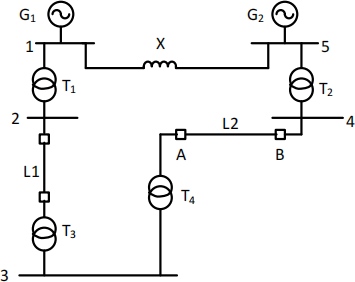
Figure Q.2 (b)
The reactance of each component is based on 100 MVA. Assume that the power system is initially unloaded, and the voltage at the transmission line is 132 kV. If a three phase fault occurs at the middle of line L2,
(i) Determine the short circuit MVA to be interrupted by the circuit breakers A and B at the end of the line. (10 Marks)
(ii) The short circuit MVA as in Q.2(b)-(i) if a three phase fault occurs through fault impedance of Zf = j0.025 per unit. (5 marks)
(iii) Comment on the effect of inserting the fault impedance on the fault point. (2 marks)
(c) The bus impedance matrix for a four-bus power system is
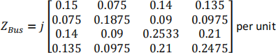
Where subtransient reactance were used to compute ZBus. Prefault voltage is 1 per unit and prefault current is neglected. A three phase short circuit occurs at bus 3 through a fault impedance of Zf = j0.025 per unit. Determine the subtransient fault current and the voltages at buses 1, 2, 3, and 4 during the fault. (5 marks)
Q.3
(a) Name and prove the fault in which all the three sequence currents are present and are equal each other. (4 marks)
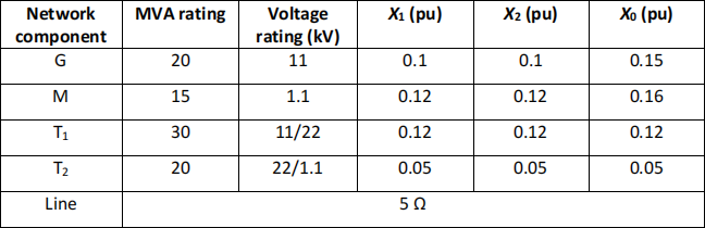
(b) Figure Q.3 (b) shows a single line diagram of a power system. The associated data of this system are given in Table Q.3. The neutral of the generator G is grounded through a reactance Xn = 0.05 per unit on the generator rating. The prefault load current and Δ-Y transformer phase shift are neglected.
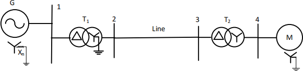
Figure Q.3 (b)
Table Q.3
(i) Draw the corresponding positive, negative sequence and zero sequence network on 30 MVA, 11 kV base in the zone of generator. (6 marks)
(ii) Reduce the sequence network to their Thevenin’s equivalent as viewed from Bus 3. (3 marks)
(c) When a single line to ground (SLG) fault with fault reactance of j1 Ω occurs at Bus 3, the prefault voltage is Vf = 1.0 ̸0° per unit. Determine:
(i) The fault current in per unit. (2 marks)
(ii) Phase voltages at point of fault in per unit. (7 marks)
(iii) If the fault (SLGF) occurs without any fault impedance (bolted fault) at bus 3, what would be the fault current in per unit. Comment on the result. (3 marks)
Q.4
(a) Discuss the determination of stability margin through swing curve observation method. (5 marks)
(b) Figure Q.4 (b) shows a one-line diagram of a power system network, and the generator is delivering 1.2 pu. A three-phase fault occurs at point F which is a distance of one-third of the length of Line 2 from generator terminal. The fault is ultimately cleared by the simultaneously opening of CB2 and CB4. Assume that the generator swings before the circuit breaker clear the fault and inertia constant, H is 4 MJ/MVA.
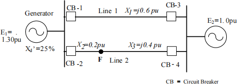
Figure Q.4 (b)
(i) Determine the power equations during prefault, faulted and postfault. (9 marks)
(ii) If the fault is cleared in 0.10 seconds, show the machine trajectory curve over a period of 0.5 seconds. (Take time step ∆t = 0.05s). (9 marks)
(iii) Based on the machine trajectory, comment on stability of the system. (2 marks)
2024-01-05