SESA2022 Aerodynamics SEMESTER 1 ASSESSMENT 2020-2021
Hello, dear friend, you can consult us at any time if you have any questions, add WeChat: daixieit
SESA2022
SEMESTER 1 ASSESSMENT 2020-2021
TITLE: Aerodynamics
DURATION: 24 hours
SUGGESTED DURATION: 4.5 hours
(including scanning and upload time).
There are three parts (Part A, B and C) to this exam. Answer ALL questions in ALL parts of the exam.
For Parts B and C:
Marks will only be awarded when appropriate work- ing is given. All sources used to answer the ques- tions should be referenced. An outline marking scheme is shown in brackets to the right of each question.
Part A - 25%
Blackboard multiple choice conceptual or simple calcu- lation questions. You will have to answer a total of 15 questions on Blackboard Assignments across the differ- ent topics in the module. Please use the link for Part A to access the questions for this part.
Part B - 50%
This question combines different topics to carry out a preliminary design calculation. The supplementary file SESA2022 2021![]() parameters.pdf gives specificdata for each student. You must use the numbers corresponding to your Student ID number. Calculations should be done accurately, using a spreadsheet, calculator or Python. It should be clearly stated when such a tool has been used. Equations from the lecture material can be used as you require. Any other resources accessed from the internet must be properly cited.
parameters.pdf gives specificdata for each student. You must use the numbers corresponding to your Student ID number. Calculations should be done accurately, using a spreadsheet, calculator or Python. It should be clearly stated when such a tool has been used. Equations from the lecture material can be used as you require. Any other resources accessed from the internet must be properly cited.
Use the template provided to create the cover page. You will need to append a scanned/photographed version of your hand-written solution method to the cover page (only hand-written workings will be accepted). The PDF should be uploaded as a Turnitin submission for Part B (which is found on the same page).
Part C - 25%
Start with the Jupyter notebook that is provided. Carry out the analytic work on paper and use the notebook to produce the required plots. Your submission should be a combination of your hand-written solution (only hand- written solution is acceptable) and plots obtained from Jupyter Notebook. Please stick to the page/size limits provided in the question. The PDF should be uploaded as a Turnitin submission for Part C.
Part B
A new start-up company called Aerialist Inc aims to de- sign and manufacture a fleet of unmanned air vehicles (UAVs) for a variety of applications. You are employed as the Aerodynamics engineer in this company and your task is to carry out a preliminary design of the wing for a UAV with the following specifications:
• Payload: W (N)
• Chord length of wing: c (m)
• Flying speed (freestream speed): U (m/s)
The values of W, c and U for your specific UAV can be found in the supplementary file.
For manufacturing and structural reasons, a rectangu- lar planform with geometric washout to ensure elliptic lift distribution has been chosen by your team. NACA 4- digit series has been chosen for airfoil sections whose camberline can be described as:
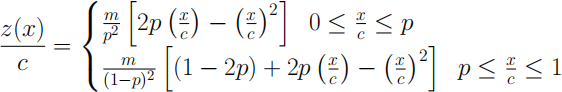
The values for m and pin the above equations can be ob- tained from the foil description. For a NACA - MP XY foil, m = 0.01M is the maximum camber (relative to chord length), p = 0.1P is the location of maximum cam- ber (relative to chord length) and maximum thickness t = XY/100 (relative to chord length). Your chosen aero- foil section can be found in the supplementary file.
The viscous flow over the wings can be assumed to be similar to that of flow over a flat plate that is inde- pendent of angle of attack and spanwise location. The transitional Reynolds number of the boundary layer is 250,000 (i.e. beyond this Reynolds number the flow will become turbulent). The pressure drag coefficient of the entire UAV based on wing planform surface area is CDP . The value of this coefficient for your UAV is in the supplementary file and does not change with angle of attack or Reynolds number.
Density of air: 1.25 kg/m3
Kinematic viscosity of air: 1.5e-5 m2 /s
Answer the following questions:
1. Calculate the zero-lift angle of attack of the foil sec- tion used in your UAV (5 Marks, one A4 side)
2. Calculate the moment coefficient about the quarter chord position for your foil section (5 Marks, one A4 side)
3. T e structural engineer needs an approximate loca- tion of the centre of pressure for your foil for further calculations. Assuming, a sample angle of attack of (see the spreadsheet for your value), find the loca- tion of centre of pressure from the leading-edge of your foil section. (5 Marks, one A4 side)
4. Compute the skin-friction drag coefficient of the wing and hence the total zero-lift drag coefficient of your UAV (15 Marks, two A4 sides)
You now need to ensure that you can achieve the highest aerodynamic efficiency for your UAV. For highest aerodynamic efficiency, determine:
5. the full span length of the wing (10 Marks, one A4 side)
6. the representative geometric angle of attack of the wing (4 Marks, one A4 side)
7. The geometric angle of attack at the root and at the tip of your wing at the value of design lift (4 Marks, one A4 side)
8. The structural engineer in your company has come back and said that you may not be able to have geo- metric twist in a rectangular planform. What can you change in order to maintain elliptic lift distribution? (2 Marks, 2 bullet points- Up to 50 words each)
COVER PAGE TEMPLATE for Part B
STUDENT ID NUMBER:
MY SPECIFIC CONDITIONS
Payload (N) =
Chord length (m) =
Freestream speed (m/s) =
Sample geometric angle of attack (degrees) =
Your foil section: NACA
m = (as inferred by you from your foil section) p = (as inferred by you from your foil section)
Pressure drag coefficient =
NUMERICAL ANSWERS:
1. Zero-lift AoA (degrees) = (2 decimal places)
2. Cm,c/4 = (4 decimal places)
3. Centre of pressure (m) = (4 decimal places)
4. Zero-lift drag coefficient = (4 decimal places)
For maximum efficiency,
5. Full span length (m)= (2 decimal places)
6. Rep AoA (degrees) = (2 decimal places)
7. AoA at
ROOT (degrees) = (2 decimal places)
TIP (degrees) = (2 decimal places)
Part C
A starting vortex with strength Γ is traveling over the ground at a height a and approaches a wall at a distance b. The origin is at the intersection of two walls. To model this a vortex in a corner, you will need to use the method of images at least twice. You will need to use superpo- sition such that the corner (with two walls at 90 degrees to each) can be represented by a streamline of the flow.
1. Write the stream function for this flow when a = b. Discuss why each vortex has the sign that it does. (6 Marks, one A4 side)
2. Plot the velocity field and streamlines of this flow. You can start from the code provided. Discuss how the plot verifies you have correctly applied the method of images. (7 Marks, two A4 sides - one for the plot, one for workings/discussion)
3. Since there is no far field velocity in this flow, we will define a characteristic velocity UΓ = Γ/(2πa). Still assuming a = b, determine the relative velocity u/UΓ and modified pressure coefficientcp = ![]() along the x-axis (which is the horizontal wall) and plot them vs x/a = -3 . . . 0 on the same plot. (7 Marks, two A4 sides - one for the plot, one for the working)
along the x-axis (which is the horizontal wall) and plot them vs x/a = -3 . . . 0 on the same plot. (7 Marks, two A4 sides - one for the plot, one for the working)
4. Using the equations and plot above, does the peak velocity equal UΓ and occur atx = -a? Discuss why or why not. Where are the minimum and maximum cp on the wall? (5 Marks, one A4 side)
2023-12-28